
User manual


RP6 ROBOT SYSTEM - 5. Experiment Board
5. Experiment Board
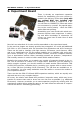
There is already an experiment expansion
module for assembling your own circuits in-
cluded in the delivery of the robot (only with
the original RP6! Not included with
RP6v2!). The module is supplied as a kit.
You will have to CORRECTLY insert and solder
the connectors by yourself. Pay special atten-
tion to the correct polarity - check the PCB's
white silkscreen printing.
Assembling your own circuits with wired com-
ponents requires some experience in solder-
ing and basic knowledge of electronics. Of
course you must have a basic idea of what
you are doing.
Now let's see what kind of circuits could be assembled on the experiment board.
In the previous chapter we already provided two examples! You could add additional
I/O Ports or A/D Channels with the described Port-Expanders and A/D-Converters.
These can be used to interface with light sensors, IR-sensors, touch-sensors, LEDs,
and so on. Additionally the I²C Bus system enables you to interface with more com-
plex sensor modules, e.g. ultrasonic distance sensors, electronic compass modules,
gyro or acceleration sensors. Other interesting sensors are pressure-, temperature-
and humidity-sensors in order to build a small mobile weather-station.
Basically the system allows you to attach any number of expansion boards to the ro-
bot. You do not have to restrict it to a single board. Whenever you are planning to
design complex systems, you should consider to install another Microcontroller. RP6
Control M32 would be a suitable device, providing your system with an extra control-
ler, 14 free I/O lines (including 6 A/D converters). The I/O-lines are available on 10-
pin connectors. You may easily assemble some flat cables to connect the module to
your expansion boards.
There are also the RP6-CC128 and M256 expansion modules, which are equally suit-
able and can serve very complex designs.
Of course, the robot's main board also provides 6 extension areas, which may be at-
tractive for sensors that need to be as low over the floor as possible (e.g. additional
IR-sensors). However we advise you to start expansion-projects by working with the
experiment module before soldering parts to the main board as removals of compon-
ents will be easier if something goes wrong...
- 123 -