
User manual


RP6 ROBOT SYSTEM - 1. Introduction
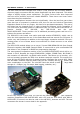
It is possible to combine the RP6v2-M256-WIFI, RP6-M32 and several of the experi-
ment PCBs – in total you would then have a Robot with 3 AVR Processors and around
80 I/O Ports for your applications. These can be connected to the Experiment PCBs via
flat cables, where you can add your own sensor electronics or ready to use sensor
modules (e.g. Ultrasonic or Infrared Rangers, Temperature, etc.). In such a setup the
strongest processor takes control of the Robot as I2C Bus master and the other two
are used as I2C Bus slaves.
For the sake of completeness it shall be mentioned that the C-Control Unit is currently
not able to be used as a I2C Bus Slave. This means the combination of several pro-
cessor modules requires the CC128 to be the I2C Busmaster. Combining the M256
and CC128 Boards is not really supported. It is theoretically possible if you use the
normal serial port (or one of the secondary ports) to command the CC128 Unit from
the M256 and put the I2C Bus into slave mode on the M256 - or not use the I2C Bus
on the C-Control Unit at all and deactivate that port.
For more information on the expansion modules, check the RP6 Website. There you
can find all related documentation and software.
Here we would like to repeat the note about the RP6 Website (this note in section 1.1
has often been overlooked in the past):
The CD-ROM can only be updated very rarely (if at all).
Software and Documentation Updates can only be found on our
Homepage:
http://www.arexx.com/
and on the robot's homepage:
http://www.arexx.com/rp6
Before you install any Software from the CD, you should check
for new Versions on the Internet!
And remember the note from the beginning of this manual:
FIRST install the USB Driver,
THEN attach the USB Interface!
- 10 -