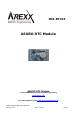
JM3-RTC33 ASURO RTC Module ASURO RTC Module ©2014 AREXX Engineering and JM3 Engineering www.arexx.com For latest updates check www.jm3-engineering.com! AREXX Engineering & JM3 Engineering Version: 1.05 Nov.
Impressum ©2012-2014 AREXX Engineering Nervistraat 16 8013 RS Zwolle The Netherlands Tel.: +31 (0) 38 454 2028 Fax.: +31 (0) 38 452 4482 This manual is protected by the laws of Copyright. It is forbidden to copy all or part of the contents without prior written authorization! Product specifications and delivery contents are subject to changes. The manual is subject to changes without prior notice. You can find free updates of this manual on http://www.arexx.
Safety recommendations IMPORTANT: Prior to using this robot arm for the first time, please read this manual thoroughly up to the end! They explain the correct use and inform you about potential dangers! Moreover they contain important information that might not be obvious for all users. - Check the polarity of the batteries or power supply. - Keep all products dry, when the product gets wet remove the power directly. - Remove the batteries or power when you are not using the product for a longer period.
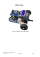
ASURO Robot Asuro xTend and Compass / Gyro module and display AREXX Engineering & JM3 Engineering Version: 1.05 Nov.
Introduction General purpose Real Time Clock (RTC) module - it can be directly plugged into the ASURO expansion port on the ASURO xTend - it can be stacked up with other ASURO extension modules like Compass/Gyro Module. The module is using the Maxim DS1339 RTC with I2C bus interface. It is a low-power clock/date device with two programmable time-of-day alarms and a programmable square-wave output. The device provides the following clock/date information - minutes, hours, day, date, month, and year.
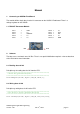
Manual 1. Connecting to ASURO xTend Board The module will be simply plug in to the K3 connector on the ASURO xTend board. There is a voltage regulator on the module. 1.1. PIN OUT Barometer Module PIN 1 PIN 2 PIN 3 PIN 4 PIN 5 = = = = = VDD n/c SQW-INT n/c n/c PIN 6 PIN 7 PIN 8 PIN 9 PIN 10 PIN1 2. = = = = = n/c SCA SCL n/c GND Pin10 Software The data access and works over I2C Bus. There is no special initialization required – refer to datasheet of the DS1339 for more information. 2.1.
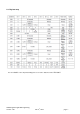
2.3. Register map For more details of the chip functionality please refer to the datasheet of the DS1339U. AREXX Engineering & JM3 Engineering Version: 1.05 Nov.
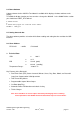
2.4. Demo Software A demo software for the ASURO xTend board is available which displays the date and time on the display. To enable the display function you have to make a change the Makefile - in the Global Defines section you should have IOEXT_RTC defined. # Global Defines # # Enable demo program for connected sensor module. DEFINES = IOEXT_RTC 2.5. Setting time and date The demo software provides a function which allows reading and setting the time and date via USB interface. 2.6.
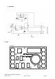
4. Schematic 5. PCB Top view: AREXX Engineering & JM3 Engineering Version: 1.05 Nov.