
User manual


RP6 Gyro Module (Yaw)
Introduction
The Gyro module converts rotations around the yaw axis and converts it to an analog
output signal. This allows you e.g. to detect that the robot is turning into the
commanded direction. Slippage can be measured depending on the software
implemented on the motion controller.
1.) Technical data:
VDD = 5.0 V +/- 5%
Vout = Vout(0) + 10mV / dps +/- 2%
Vout(0) = 2,5 V +/- 2% (no motion)
Range = approx.. 200dps max
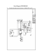
2.) Pin out:
Pin 1 (K2)
Pin 1 (K1)
PIN1 K2 = VDD PIN1 K1 = SLEEP/PD
PIN2 K2 = n/c PIN2 K1 = ST
PIN3 K2 = GND PIN3 K1 = n/c
PIN4 K2 = OUT PIN4 K1 = n/c
3.) Connecting to RP6WIFI or RP6 Robot.
Connect PIN1/K2 of the module to VDD (5.0V) and PIN3/K2 to GND - watch out
reverse polarity! Choose a free ADC input of your RP6 Robot or WIFI board and
connect it to PIN4/K2 OUT which provides the signal. In addition you need to control
the PIN1/K1 SLEEP/PD and PIN2/K2 ST to enable the operation of the module.