
User manual


AREXX Engineering & JM3 Engineering
Version: 1.43 Nov 9
th
, 2014 page: 9
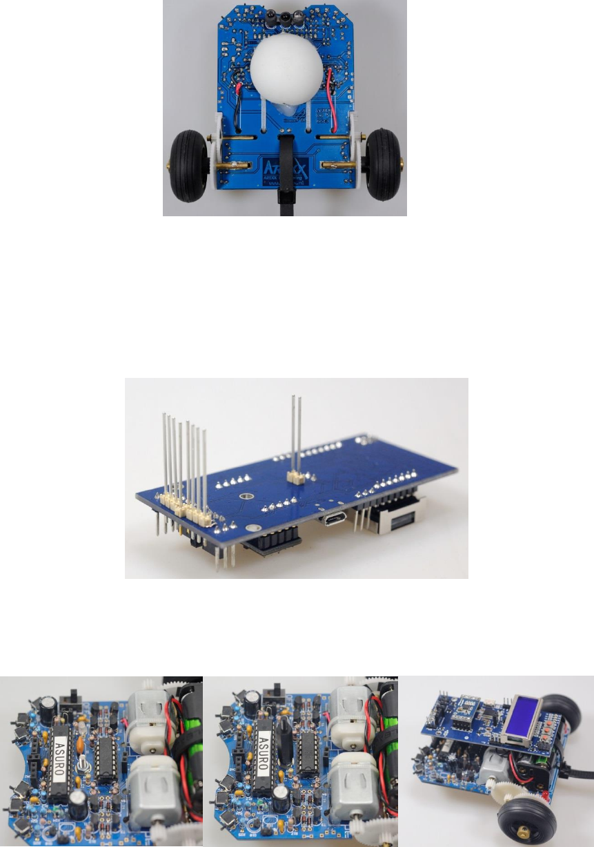
Step 3
Modify the motor wiring on the Asuro board. Use one of the holes to bring the wires down
to the bottom side of the PCB and solder them to the motor driver output from the bottom.
Take care of the polarity of the wires – it may case wrong turn direction of the motors.
Step 4
Solder the connectors to the Asuro base into the Asuro xTend board. Watch out they are
right-angled in both axis.
Hint: Tilted contacts may cause problems contacting the Asuro XTend board to the
Asuro Robot.
Step 5
Assemble the screw and the distance pole as shown. Plug in the pre-assembled Asuro
xTend board into the contacts on Robot and lock them with a nut.