
User manual


AREXX Engineering & JM3 Engineering
Version: 1.43 Nov 9
th
, 2014 page: 8
2.2. Asuro – Setup
Step 1
Solder the extension board connectors into the Asuro. If you had used the Line-Follower
(T9, T10 and D11) before, than remove them carefully (de-soldering tool or de-soldering
braid!) and re-fit them after the assembly of the connectors.
For a better line follower performance you should replace the D11 with an IR 950ns
spectrum like TSUS5400 (Vishay).
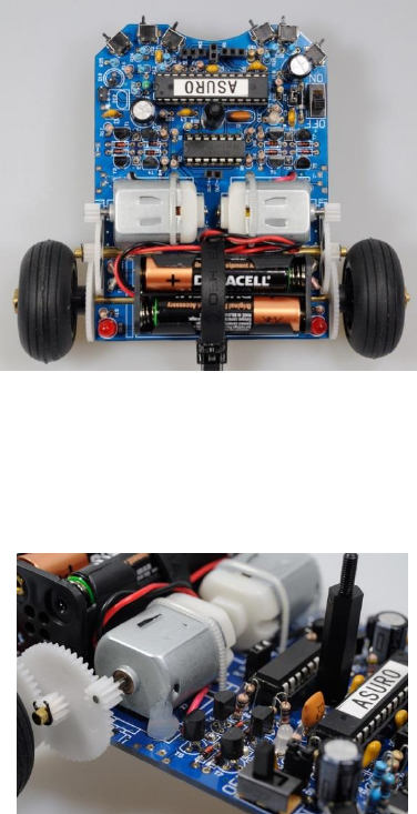
Step 2
Dis-assemble the motors and mount them top down (contacts to the bottom).
Fix the motors mechanically using a wire straps and hot glue.
HINT: Step 2 and Step 3 are only required if you want to reduce EMI influence of the
motors.