
User manual


AREXX Engineering & JM3 Engineering
Version: 1.43 Nov 9
th
, 2014 page: 6
Manual
1.1. Hardware configuration and setup
The Asuro xTend Board is designed to support a master / slave configuration together with the
Asuro, but it is not limited to.
This description provides guidance for the setup and the functional behavior as mater/slave
configuration. The Asuro Robot works as a MASTER I2C device ‘pulling’ the new direction/speed
information from the Asuro xTend Board (SLAVE). It computes the drive relevant algorithms
(speed detection/regulation) and delivers the battery voltage, speed and switch information. In
addition, the power and interface signals are provided to the Asuro xTend board.
The Asuro xTend board collects the sensor signals from the various sources, e.g. Gyro,
Compass, Sharp-Sensors and so on.
HINT: It is highly recommended to use a display.
The compass must be calibrated by a build in function and procedure.
On the Asuro Extension Bus you have all signals from the Asuro, but with a second I2C Bus
working independent from the Asuro Main Board with the other extension seamless together.
The Display can show status messages or other system status information. The menu can be
controlled via the 3 buttons – 4 LEDs are additional ‘indicators’.
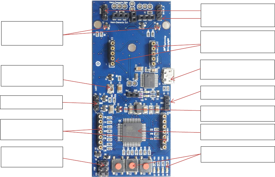
1.2. Board overview
S1 S2 S3 LED1 - LED4
Distance sensor option
Sharp (Left & Right)
Sensor Module header
2 Ch. Power switch
for SHARP sensor
ATXmega32C4
Display contrast
adjustment
3.3V regulator
USB Programming IF
Connector
Display IF
(EA DIPS082)
Debug IF
(PDI, optional)
3 Button & 4 LED
ADC / GPIO header
Ext. UART header