
User manual


AREXX Engineering & JM3 Engineering
Version: 1.43 Nov 9
th
, 2014 page: 10
Step 6
Plug in the Asuro Compass / Gyro Module and calibrate the sensor (north, east, south
west)
HINT: This step is only applicable if you own the Compass module as well.
Step 7
Load the Asuro demo software (hex-file) for the base using the IR transmitter and then
load the Asuro XTend demo software via USB IF with the new JM3 Robot-Tool (refer to
chapter 4 for more details).
Step 8
Calibration of the 3D Compass:
1. Switch on the Asuro and press button S1 and go to the Heading screen (HD).
2. Use a normal compass to determine the direction to north, east, south and west.
Remember the points.
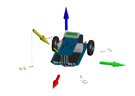
The figure shows the virtual axis relative to the Asuro. The x-axis is red, the y-axis is
green and the z-axis is blue. The inclination vector is marked yellow.
The angle of this vector is not precisely known and varies with the location on the earth.
If the inclination vector and the x-axis vector are in line we can expect the maximum of
the measured signal, which is important for a good calibration.
3. Press S3 until the red LED (LED4) illuminates to start the calibration.
Point to north and tilt the Asuro plus 90° and minus 90°. Then tilt to the left and right
side of the Asuro. Repeat this procedure for east, south and west.
4. After this process press S3 short to finalize the calibration. The calibration data are
stored in the EEPROM.
Hint: It is recommended to use a display!
Tilt the Asuro not too fast during calibration – this will negatively influence the
accuracy of the heading.