JM3-AXT3 Asuro xTend Asuro xTend Board ©2014 AREXX Engineering and JM3 Engineering www.arexx.com For latest updates check www.jm3-engineering.com! AREXX Engineering & JM3 Engineering Version: 1.
Impressum ©2012-2014 AREXX Engineering Nervistraat 16 8013 RS Zwolle The Netherlands Tel.: +31 (0) 38 454 2028 Fax.: +31 (0) 38 452 4482 This manual is protected by the laws of Copyright. It is forbidden to copy all or part of the contents without prior written authorization! Product specifications and delivery contents are subject to changes. The manual is subject to changes without prior notice. You can find free updates of this manual on http://www.arexx.
Safety recommendations IMPORTANT: Prior to using this robot arm for the first time, please read this manual thoroughly up to the end! They explain the correct use and inform you about potential dangers! Moreover they contain important information that might not be obvious for all users. - Check the polarity of the batteries or power supply. - Keep all products dry, when the product gets wet remove the power directly. - Remove the batteries or power when you are not using the product for a longer period.
Asuro Robot with Sensor Module Asuro xTend board and Compass / Gyro module & Display AREXX Engineering & JM3 Engineering Version: 1.
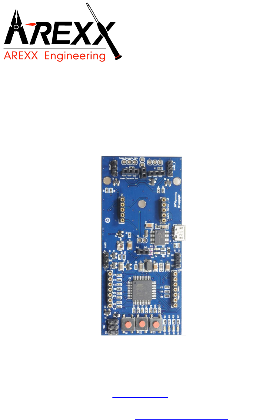
Introduction The new Asuro xTend board provides multiple extension possibilities. The core is the very powerful ATXMega micro-controller with 32KB Flash & 4KB SRAM running at 16MHz Clock with low power consumption and several interrupt inputs. The Asuro Robot has got new features with the Asuro xTend extension as following: extended interfaces to the Asuro Robot, the improved Asuro Ext.
Manual 1.1. Hardware configuration and setup The Asuro xTend Board is designed to support a master / slave configuration together with the Asuro, but it is not limited to. This description provides guidance for the setup and the functional behavior as mater/slave configuration. The Asuro Robot works as a MASTER I2C device ‘pulling’ the new direction/speed information from the Asuro xTend Board (SLAVE).
The Asuro xTend board provides multiple new possibilities: Features - ATXmega controller with 32+4KB Flash, 4KB SRAM, 2KB EEPROM - 2nd independent IC2 Master IF for other extensions - display interface with trimmer for contrast and display illumination control - 2 x Sharp Sensor ports with power ON/OFF capability with mounting holes - 3 Buttons - 4 LEDs (2 red, 1 yellow and 1 green) - Line Follower Sensor on Asuro board (automatic switching of signals) - PDI debug IF (optional) - PRG-UART via build in US
2.2. Asuro – Setup Step 1 Solder the extension board connectors into the Asuro. If you had used the Line-Follower (T9, T10 and D11) before, than remove them carefully (de-soldering tool or de-soldering braid!) and re-fit them after the assembly of the connectors. For a better line follower performance you should replace the D11 with an IR 950ns spectrum like TSUS5400 (Vishay). Step 2 Dis-assemble the motors and mount them top down (contacts to the bottom).
Step 3 Modify the motor wiring on the Asuro board. Use one of the holes to bring the wires down to the bottom side of the PCB and solder them to the motor driver output from the bottom. Take care of the polarity of the wires – it may case wrong turn direction of the motors. Step 4 Solder the connectors to the Asuro base into the Asuro xTend board. Watch out they are right-angled in both axis. Hint: Tilted contacts may cause problems contacting the Asuro XTend board to the Asuro Robot.
Step 6 Plug in the Asuro Compass / Gyro Module and calibrate the sensor (north, east, south west) HINT: This step is only applicable if you own the Compass module as well. Step 7 Load the Asuro demo software (hex-file) for the base using the IR transmitter and then load the Asuro XTend demo software via USB IF with the new JM3 Robot-Tool (refer to chapter 4 for more details). Step 8 Calibration of the 3D Compass: 1. Switch on the Asuro and press button S1 and go to the Heading screen (HD). 2.
2.3. Display modification to control illumination In case of you are using the backlit LCD you have to make the changes as shown. Use the component R5 or R6 (0 ohm resistor) to put it on the position of R7. The change is not required – you just can control the illumination. 1. Remove R5 / R6 Hint: 2. Place R7 The changes requiring average soldering skills with SMT components! Do some soldering test before, if you doesn’t feel well enough with such changes.
The software can be complied with the GNU AVR and the source code can be edited with Notepad+ or Visual Studio Express (free download at Microsoft) – the makefile is included. The GCC Tool chain is included – see avr-gcc-4.8.1.zip. Extract to C:\GCC and run addpath.exe to make the correct settings automatically. More detail how to install the Tool Chain please refer to avr-gcc-vs.pdf. 3.
3.2 Asuro The Asuro itself will be used as the ‘motor controller’. The JM3 Asuro Base SW is provided in the package and must be only one time programmed into the Asuro (assuming you don’t want to change the drive control algorithm or something else on the low level drivers). All application changes will be programmed on the ASRUO xTend Board which provides much better performance and capabilities.
4. JM3 Robot-Tool 4.1. Programming the Asuro xTend To program the demo code into the xTend Board you have to install the JM3 Robot Tool and perform the following steps: 1. Copy the JM3 Robot Tool in a folder and start the program (exe –file). 2. Click on the ‘Add Robot’ icon – enter a name, set the Hostname e.g. COM5 and 3. Select the type to AsuroExt. The right COM number you can look up in the Device Manager – the number depends on your PC configuration! 4. Click OK 5.
5. Connector PIN-OUT 5.1. Connectors to Board K5: (Asuro Connector Main) PIN 1 = VCC PIN 2 = GND PIN 3 = AIN0 PIN 4 = RGND PIN 5 = OC PIN 6 PIN 7 PIN 8 PIN 9 PIN 10 = = = = = V+2 SDA_M V+1 SCL_M INT0 5.2.
6. Technical data 6.1. Supply voltage / current consumption (bus not active, no other connections rather than supply voltage and GND). VCC ICC = = 5,0 V 20 mA ± 2% ± 5,0mA (w/o display and additional sensors) 6.2. Power switches: Iout max = 0.5 A / continuous each channel / peak 1,0A (2 channels are active at the same time) 6.3. I2C Bus speed (MASTER & SLAVE): 400kHz max. 6.4. All other data according to IC data sheets (see chap. 3.6) AREXX Engineering & JM3 Engineering Version: 1.
7. Schematic AREXX Engineering & JM3 Engineering Version: 1.
AREXX Engineering & JM3 Engineering Version: 1.
8. PCB AREXX Engineering & JM3 Engineering Version: 1.