
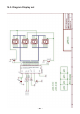
Instructions Circuit Diagram


- 96 -
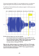
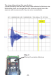
The second signal red (CON1-15), an unloading curve, is a reference
signal coming from the ultrasonic PCB. It returns to the processor.
Ifareectionndsitselfabovethereferencesignal,itwillbeseenasa
valid measurement.
On the above image you see two signals:
- the already mentioned red reference signal CON1-13 and
- the receiving blue signal CON1-6 (the signals received and
reected by the ultrasonic PCB, then going to the
microprocessor through CON1-6).
We mark the reected signal at a distance of 60 cm. All strongly
reected signals are located above the reference line as a result
of undesired direct reections of YETI. These signals therefore
cause an invalid measurement.
60 cm