
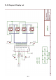
Instructions Circuit Diagram


- 95 -
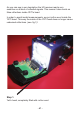
14.8. Preparation YETI Ultrasonic Set
The assembled ultrasonic PCB is mounted in the YETI head. However,
inthislocationthefunctioningofthisultrasonicsetwillbeinuenced
by:
1. UndesiredreectionsoftheultrasonicsoundinsidetheYETI
head.
2. Undesiredreectionsoftheultrasonicsoundbytheoutsideof
YETI itself.
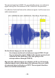
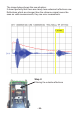
Belowyoundtwoimportantultrasonicsignals:
On this oscilloscope image you see two signals, measured on CON1-
13 and CON1-15.
Therstsignalblue(CON1-13)brieyshows5pulsesofapprox.4.5
Volt. The signal comes from the microprocessor directly and goes to
the ultrasonic PCB.