
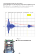
Instructions Circuit Diagram


- 94 -
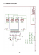
The ultrasonic signal will now be applied to one entry port of two
opamps.Theotherentryportsofbothopampsaresuppliedwithaxed
voltage reference of exactly 50% of the supply voltage. Both opamps
are needed to generate a maximal energy for the loudspeaker and to
regenerate the weak and distorted microphone signal. The ultrasonic
microphone(RX)detectsthereectedsignalandtransformsitintoan
electronicsignal,whichmaybelteredandampliedinreceiveram-
plierOpampIC1B.Anadjustableresistorallowsyoutocontrolthe
amplicationfactorofthesystem.
As resistor R3 leads the ultrasonic output pulses to the loudspeaker,
the signal will also pass diode D1 and load capacitor C7 immediately to
a full suply voltage value VCC, leading to a sharp raise of a voltage at
pin CON1-15 at the beginning of transmission impulses. At the trailing
edge of the transmission impulse capacitor resistor R14 will discharge
C7.
The microcontroller contains an analogue comparator in order to com-
pare two voltage levels: the received signallevel at pin CON1-6 and
the decreasing voltage level at pin CON1-15.
If the received signal level exceeds the decreasing voltage level at pin
CON1-15,themicrocontrollerwillacceptthesignalasavalidreection
signal. Using the decreasing comparision level will result in high vali-
dationsignallevelsforfastresponsereectionsandgraduallylower
validationsignallevelsforretardedresponsereections.
Of course the ultrasonic receiver system is extremely sensitive for
anyreectedsignals,especiallyforsignalsfromnearbyobjectsinthe
transmitter’s vicinity.
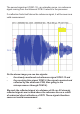
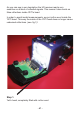
InordertopreventreectionsfromtheYETI’sheadsurroundingtheul-
trasonictransmitterandreceiver,wewillcompletelylltherobot’shead
with cotton wool, including the volume between the band cable and the
backofthehead.Seegure1.