
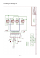
Instructions Circuit Diagram


- 93 -
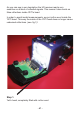
14.7. Hardware description
The ultrasonic module consists of 5 parts:
1. Transmitter
2. Receiver
3. Receiveramplier
4. Fixed voltage reference
5. Variable voltage reference
The microcontroller generates the ultrasonic signal wave to be trans-
mitted by the transmitter loudspeaker (TX). The receiver microphone
(RX)receivesreectedsoundwaves,whichmustbeampliedinthe
receiveramplier.ResistorR10allowsyoutomanuallycontroltheam-
plicationfactor.Thexedvoltagereference,whichisexactlyadjusted
to 50 % of the supply voltage, will be used for the transmitter and for
generating the variable voltage reference.
The variable voltage reference controls the hearing sensitivity. On
every transmission impulse the microcontroller will adjust its sensitivity,
increasing sensitivity with delay and distance. A growing distance will
resultinweakerreectionssignalsandingrowingdelaysaswell.
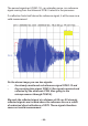
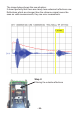
The microcontroller generates the ultrasonic signal wave, entering the
ultrasonicmoduleatpinCON1-13.Thereectedsignal,asmonitored
in the microphone, is returned to the microcontroller by pin CON1-6. At
any transmitted impulse, pin CON1-15 will ramp down a voltage signal
for the microcontroller validation.
Of course the microcontroller will not generate an acoustic but an elec-
tronic signal. In fact the loudspeaker will generate the ultrasonic sound
waves from the electronic signal.
The generated ‘ultrasonic’ signal will leave the microcontroller and
enter the transmitter module by CON1-13 and resistor R3. The trans-
mitterconsistsof2individualampliersinachipIC1(IC=Integrated
Circuit),containingatotalof4ampliers.Inelectronicstheseampliers
arenamedOpamp(OperationalAmplier),containingadifferential
amplierstageusingtwoinputports:apositiveandanegativeentry
port.Thedifferentialamplierstagewillprocessthevoltagedifference
between both ports and the opamp’s output voltage will be proportional
to the voltage difference between both ports.