
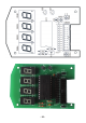
Instructions Circuit Diagram


- 88 -
Additionally each display provides a common supply pin for the LED’s.
Four segments each share a common supply pin and both supply pins
3 and 14 are interconnected internally.
In order to provide control signals for 4 display units we normally would
need at least 8+2=10 signal lines for each symbol, requiring a 40-pin
IC. However we can use a tricky multiplex system, providing 2 sets of
8-segmentpins:P1-P8andP9-P16.Let’srsthavealookattherst
set P1-P8, which is connected to display 1 and display 2 simultaneous-
ly. Feeding P1-P8 with a certain bit combination for a special display
symbol, e.g. “X”, the units 1 and 2 would both display the same symbol
“X”. Now we just need to activate display 1 and to deactivate display 2
with switching transistor Q1 and Q2, merely activating display 1.
In a next step the chip will switch off display 1 by deactivating transistor
Q2, provide a new bit combination for a new display symbol, e.g. “Y”,
feeding the combination to P1-P8, and switch on transistor Q1 to ac-
tivate display 2. The same procedure will be used for display 3 and 4.
Using a high switching rate, which is invisible to the human eye, we will
not be able to observe the 50% dark phases, in which the symbols are
switched off. The human eye will see the display symbols constantly at
a reduced intensity.
An alternative display method allows using two displays without multi-
plexing. These displays can be activated without switching on and off.
To do so one display (Display 1) must be using P1-P8, whereas the
other display (Display 3) will be using P9-P16. The software example
suggests the display units will be arranged in a special way:
Display arrangement:
Display 4 Display 2 Display 3 Display 1
The basic idea of the arrangement for using two display units (display
units 1 and 3) in a static mode is the requirement these elements must
be neighbours.