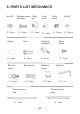
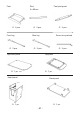
Instructions Circuit Diagram
Manuals
Brands
Arexx Manuals
Build-Your-Own Robot Kits
Arexx YETI Programmable Walking Robot
21
22
23
24
25
26
27
28
29
30
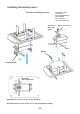
- 24 -
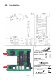
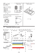
Fig. 5.1.: Layout RS232- Infrared-T
ransceiver
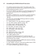
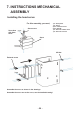
Finally check the board for short circuits or polarity errors.
Check the soldering quality intensively and re-solder bad contacts.
5.9.
Layout RS232-Infraread-T
ransceiver PCB
1
...
...
22
23
24
25
26
...
...
121