
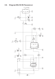
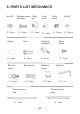
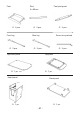
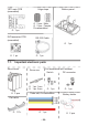
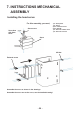
Instructions Circuit Diagram

- 22 -
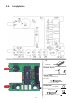
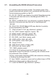
5.7. Assembling the RS232-Infrared-Transceiver
• IC1: Initially insert the 8-pole socket. The polarity mark of the
(slightly asymmetrical) socket must correspond with the mark in
the accompanying symbol on the PC.
• D1, D2, D3: 1N4148, pay attention to polarity! Read the imprints
of the parts and take care not to interchange with ZPD5.1 or
BZX55-C5V1!
• D4: ZPD5.1 or BZX55-C5V1, pay attention to polarity! Read the
imprints of the parts and take care not to interchange with
1N4148!
• D5: SFH-415-U IR LED (Black LED) pay attention to polarity,
press downwards to the PCB
• C1: 100µF at least 16 Volt, pay attention to polarity!
• C2, C4: 100nF ceramic capacitor, imprint: 104
• C3: 680pF ceramic capacitor, imprint: 681
• Q1: BC547 (A,B or C) or BC548 (A,B or C)
• R1,R5:20kΩ_(red,black,orange,gold)
• R2:4.7kΩ(yellow,violet,red,gold)
• R3:470Ω(yellow,violet,black,gold)
• R4: Does not exist
• R6:10kΩ(brown,black,orange,gold)
• R7:220Ω(red,red,brown,gold)
• TR1:10KΩvariableresistor
• IC2: SFH5110-36 Infrared receiver IC, bend the legs with
appropriate tongs! Pay attention to polarity (the curvature must
be positioned to the outside)!
Caution: electrostatic discharge (ESD) and excessive soldering
or heating may damage the part!
• X1: 9pol. SUB-D connector, case must be settled close to PCB.
Attachment strips must be soldered as well!
• IC1: insert the NE555P, pay attention to polarity!