
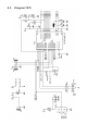
Instructions Circuit Diagram


- 13 -
4. HARDWARE
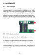
4.1. YETI main PCB
YETI’s main printed circuit board (PCB) is equipped with an Atmega8L
microcontroller chip. The microcontroller is connected to a big, round
beeper and to both red LED’s at the front side. A great number of other
microcontroller pin connections, e.g. the I2C bus, are routed to the
20-pin connector at the rear side directly. This connector provides an
extensionporttootherhardwarebyaatcable.Bothblackconnec
-
tors next to the red LED provide the connections to both servos. Three
white connectors serve the connectors for the main switch and for both
battery packs.
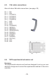
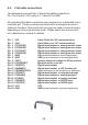
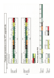
4.2. Flat cable connections
Thedesignersreservedfourofthetwentyatcableconnections.
Pin 19 is used for VCC and pin 7, 8 and 20 for GND.
Allremainingatcableconnectionsareconnectedtoadedicated
microcontroller pin. The pin numbers are listed with the assigned
microcontroller pin functions.
Microcontroller pins may be used in several modes, depending on the
programming mode. Please check the microcontroller’s datasheet or
manual for details.