
Instructions Circuit Diagram


- 115 -
H. ERROR TRACING
H.1. GENERAL
Check all parts for correct polarisation and correct value. Check soldering connections
for short circuits and bad soldering. Has a soldering pad been disrupted ?
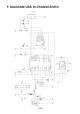
If all checks have been made without results, the bad part has to be traced with
the help of the schematic (see Appendix) and an adequate measurement device
(multimeter or oscilloscope).
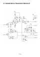
H.2. Failure of the RS232-IR-transceiver
- Activated key and displayed symbol do not match
Calibrate Trimmer TR1 until activated key and displayed symbol do match.
- The terminal program does not display any symbol
Has the timer-IC (IC1) been inserted and has it been inserted correctly polarized (the
mark must point to the three diodes) ? Take any infrared remote control of a HIFI- or
video-equipment (videorecorder, TV, etc) and point it to the IR-transceiver, pressing a
few keys. If the terminal program displays irregular symbols, the receiver (IC2, R3, C4,
D4, T1) is operating. All other parts have to be checked.
Still not working
(In most cases one of the components IC1, IC2, Q1, D4 may have been damaged).
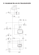
H.3. USB-infrared-tranceiver does not work
WINDOWS
Check if the drivers are installed correctly and if the correct com port is selected.
LINUX
Disconnect the USB transceiver... wait a minute and connect it again, this may solve
the problem.
An other option is to install a new kernel