Walking robot YETI Manual: Model YT-3000 © AREXX - THE NETHERLANDS V01082006 - -
CONTENT 1. 2. 3. 4. 6. 7. 8. 9. 10. 11. 12. 13. 14. Produkt description YETI 3 YETI general information 4 Who or what is YETI? 11 Hardware 13 Assembly instructions electronics 17 Partlist mechanics 26 Mechanical assembly instructions 29 Charching YETI batteries 41 Software installation and initial steps 48 Preparation for operation 63 YETI Calibration 66 YETI Programming 69 Extensions and upgrade modules 85 xx. APPENDIX 104 A.
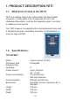
1. PRODUCT DESCRIPTION YETI 1.1. What kind of robot is the YETI? YETI is a walking robot man, named after “the abominable snowman”, a hairy giant, who is supposed to live in the Himalayan Mountains. Just like the legendary giant, our robot is walking on two big feet. Our YETI however is supplied with a microprocessor brain and a computer program, controlling a number of servomotors to move its legs and feet. 1.2.
2. YETI GENERAL INFORMATION 2.1. Who or what is YETI? As already mentioned YETI is a walking robot, named after “the abo-minable snowman”, a hairy giant, who is supposed to live in the Himalayan Mountains. Just like the legendary giant, our robot is walking high on his two big feet. Our YETI however is supplied with a microprocessor brain and a computer program, controlling a number of servomotors to move its legs and feet. So it can walk forwards and backwards and even make left and right turns.
2.2. How can we use the YETI robot? • • • Load different example programs into the YETI. Load self-made programs into the YETI. Add assembled electronic extension units to enable the YETI to avoid obstacles or to measure distances. Add self-made electronic extension units. Let YETI communicate with your computer by wireless infrared signals. Control YETI by wireless infrared signals from your computer or from your remote TV-control set.
2.3. YETI may be activated by 3 simple steps 1. Assemble the mechanic and electronic modules of YETI following the instructions in the manual. If you use accumulator-packs, charge the rechargeable devices to 100 %. Activate the main YETI switch at the bottom of the robot. 2. 3. A few seconds later YETI will stretch his legs and proceed by giving a demonstration of his abilities, following a standard example program in the processor’s memory.
2.4. Loading an example program into the YETI memory We will be using harmless invisible infrared light signals to load an example program into the YETI memory. In fact, the supplied COM-port adapter contains a RS232-infrared transceiver, which must be connected to the COM-port of your PC. The YETI robot contains a built-in infrared transceiver, being located behind both small openings at the robot’s back. The computer COM-port adapter is available as an USB-module as well.
2.5. Loading a YETI program into the robot • Connect the COM-port adapter (or the USB adapter) to your PC. Start the Flash program at the computer. Select the COM-port for the COM-port adapter in the Flash program at the computer. Select the YETI program in the Flash program. Allow the holes in the YETI’s back to be directed to the upper side of the COM-port adapter. Switch off YETI’s main switch. Press the button “Programming” in the Flash program. Switch on YETI’s main switch (within 10 seconds).
2.6. Add-on kits You may easily add extra (but non included) modules to the YETI robot, to allow YETI to do much more. How about adding an ultrasonic transceiver, allowing YETI to sense the distance to obstacles and avoid these objects while walking around? You also may add a display to YETI’s body to show output messages or data. Add-on kits usually contain a printed circuit board (PCB) and may be supplied with or without electronic components.
2.7. The communication between YETI and PC Pressing the “Programming”-Button in the Flash Program will activate the Flash program to contact the YETI robot for 10 seconds. If YETI responds, the YETI program will be transferred. YETI however will only respond to the PC if the contact is tried within a 3 seconds period following YETI’s switch on. If YETI is not being contacted within the 3 seconds period, the robot will proceed by starting the program in its memory.
4. WHO OR WHAT IS YETI? 4.1. Summary As discussed in the first chapter the YETI is a mythical figure, the abominable snowman, living in the Himalya Mountains and clumsily walking on two big feet. Our YETI is a tall, upright standing robot, equally walking on two big feet and being able to move forward or backward or make a left or a right turn. Every step forward or backward will start by balancing on one foot and moving the opposite foot. Basically two servos will be executing these movements.
Detailed explanation Starting from stillstand, the YETI starts rotating the feet servo clockwise as seen from the front side. These rotations will result in two movements: In a first phase the rigth side of the feet servo is rising, pulling the outer side of the right foot upwards. This action might bend the body to the right, but this movement is impossible as long as the main part of the weight is still resting on the inner side of the right leg.
4. HARDWARE 4.1. YETI main PCB YETI’s main printed circuit board (PCB) is equipped with an Atmega8L microcontroller chip. The microcontroller is connected to a big, round beeper and to both red LED’s at the front side. A great number of other microcontroller pin connections, e.g. the I2C bus, are routed to the 20-pin connector at the rear side directly. This connector provides an extension port to other hardware by a flat cable.
4.3. Flat cable connections More info about flat cable connections: (see page. 20) Pin 1 SCL Pin 2 SDA Pin 3 PC3(ADC3) Pin 4 PC2(ADC2) Pin 5 PC1(ADC1) Pin 6 PC0(ADC0) Pin 7 GND Pin 8 GND Pin 9 AVCC Pin 10 PC6(RESET) Pin 11 PB5(SCK) Pin 12 PB4(MISO) Pin 13 PB3(MOSI/OC2) Pin 14 PD3(INT1) Pin 15 PD6(AIN0) Pin 16 D7(AIN1) Pin 17 PD0(RXD) Pin 18 PD1(TXD) Pin 19 VCC Pin 20 GND 4.4.
4.5. Flat cable connections The designers reserved four of twenty flat cable connections. Pin 19 is used for VCC and pin 7, 8 and 20 for GND. All remaining flat cable connections are connected to a dedicated microcontroller pin. The pin numbers are listed with the assigned microcontroller pin functions. Microcontroller pins may be used in several modes, depending on the programming mode. Please check the microcontroller’s datasheet or manual for details.
- 16 -
5. ASSEMBLY INSTRUCTIONS ELECTRONICS First of all please check if all parts in the kit are complete. 5.1. Soldering job The layout on the PCB clearly shows where to mount each component. When you want to see more detailed information, please study the diagram, pictures and drawings for extra help and information. When we assemble a PCB we always start with the lowest passive components. Normally these are the resistors followed by the capacitors.
CAUTION • Read this manual carefully in advance to fully understand how to assemble this product. • Children below 14 should can only assemble this product with the help of adults. • Be careful about tools. Especially be careful about sharp tools such as nippers or cutter knife to prevent any injuries or accidents. • Never assemble the kit when a younger child is around. The child might touch sharp tools or swallow parts and a vinyl bag. • Be careful about sharp edges of parts.
5.4. Assembly main PCB IMPORTANT see 5.5 (Diagram) and 5.6 (Pictures) YETI parts list Nr. Name Pcs. PCB1 Main PCB 1 IC1 ATmega8-l (polarity!) 1 IC2 SFH5110 IR-receiver-IC (polarity!) 1 R1 10K / 0.25W / 5% (Brn, blk, or, gld) 1 R2 120K / 0.25W / 1% (Brn, red, blk, or, brn) 1 R3 100K / 0.25W / 1% (Brn, blk, blk, or, brn) 1 R4 220R / 0.25W / 5% (Red, red, brn, gld) 1 R5 220R / 0.25W / 5% (Red, red, brn, gld) 1 R6 470R / 0.25W / 5% (Ylw, vio, brn, gld) 1 R7 470R / 0.
6.3.
5.6. Hauptplatine IC IC Marking + Resistor & Coil Marking with color stripes. + LED & IR-LED The side with the flat marking is the Cathode. The long leg is the e Anode.
5.7. Assembling the RS232-Infrared-Transceiver • IC1: Initially insert the 8-pole socket. The polarity mark of the (slightly asymmetrical) socket must correspond with the mark in the accompanying symbol on the PC. D1, D2, D3: 1N4148, pay attention to polarity! Read the imprints of the parts and take care not to interchange with ZPD5.1 or BZX55-C5V1! D4: ZPD5.
5.8.
5.9. Layout RS232-Infraread-Transceiver PCB Fig. 5.1.: Layout RS232- Infrared-Transceiver Finally check the board for short circuits or polarity errors. Check the soldering quality intensively and re-solder bad contacts.
5.10. Info assembled USB-Infrared-Transceiver The USB-IR-Transceiver is also available already assembled. Fig 5.2.: USB Infrared-Transceiver Fig. 5.3.: Component layout USB-Infrared-Transceiver Fig. 5.4.
6. PARTS LIST MECHANICS Flathead screw Collar big M3x8mm Nut M3 O 8 pcs. O 8 pcs. O 4 pcs. Rivet Screw-rod connector O 4 pcs. O 4 pcs. O 2 pcs. Ball-end screw Ball adjuster Ballhead screw O 4 pcs. Nut M2 O 10 pcs. O 10 pcs. O 4 pcs. Spacer O 4 pcs. Collar screw Colar small Servo Screw O 2 pcs. HEX-tool O 4 pcs. O 1 pc. Thread end rod short Thread end rod long O 4 pcs. O 2 pcs.
Foot Rod 5 x 80mm O 2 pcs. Front leg O 2 pcs. Feet joint panel O 2 pcs. O 2 pcs. Rear leg Servo arm pushrod O 2 pcs. O 2 pcs. Top panel Top cover panel O 1 pc. O 1 pc. Head panel Back panel O 1 pc. O 1 pc.
YETI main PCB (assembled) O 1 pc. IR/Transceiver PCB (assembled) Velgro-tape Bottom panel O 2 pcs. Male O 2 pcs. Female Pre-assembled RS-232 Cable O 1 pc. O 1 pc. 7.1. O 1 pc. Important electronic parts Servo motor Pre assembled with cableset Servo arm Switch O 1 pc. 1mm O 1 pc. 2mm O 2 pcs. O 1 pc. Cable set, Pre-assembled DC-connector O 1 pc. Battery holder Flat cable O 1 Pc. O 1 pc. - 28 - O 2 pcs.
7. INSTRUCTIONS MECHANICAL ASSEMBLY Installing the head servo: For this assembly you need; Servo Arm with 2mm holes Servo screw 1 pc. Head panel 1 pc. Servo 4 pcs. Flathead screw 4 pcs. Nut M3 1 pc. Servo arm 2mm holes 1 pc. Servo arm screw Servo M3 Nut Flathead screw Assemble the servo as shown in the drawings.
Installing the bottom servo: For this assembly you need; 1 pc. Bottom panel 1 pc. Servo 4 pcs. Flathead screw 4 pcs. Nut M3 1 pc. Servo arm 1 pc. Servo arm screw Servo Arm with 1mm holes Servo arm screw Servo M3 Nut Flathead screw Servo Arm with 1 mm holes Assemble the servo as shown in the drawings.
End assembly bottom panel: For this end assembly you need; 1 pc. Assembled bottom panel 1 pc. Switch 1 pc. DC connector 2 pcs. Battery holder 4 pcs. AA accu 2 pcs. Velgro-tape male 2 pcs. Velgro-tape female IMPORTANT! Do not forget to insert the batteries before you close the YETI back panel! Installing Velgro-tape (normally Pre-installed) Battery holder DC connector Switch Assemble the bottom plate as descriped in the drawings.
Assembly YETI head: For this final assembly you need; 1 pc. Assembled bottom panel 1 pc. Assembled head panel 1 pc. Assembled main PCB 1 pc.
Installing the wires: For the wire assembly you need; 1 pc. Assembled bottom panel 1 pc. Assembled head panel 1 pc. Assembled main PCB Assembled cable set with: 1 pc. Wire back 1 pc. Wire blue 1 pc. Wire yellow 1 pc. Wire red Install all wiring as shown in the drawings.
Cable connections main PCB: JP1 & JP2 Servo Connections 1. White 2. Red 3. Black 1.
Mechanical end assembly YETI head: For this final head assembly you need; 1 pc. Assembled YETI head 1 pc. Top panel 1 pc. Top cover panel 4 pcs. Thread end rod, short 4 pcs. M2 Nut 4 pcs. Spacer 4 pcs.
Legs and Feet assembly: For the legs and feet assembly you need; 2 pcs. Foot 2 pcs. Front leg 2 pcs. Back leg 2 pcs. Feet joint shaft 2 pcs. Rivet 2 pcs.
YETI Leg Assembly part I: For part I of the leg assembly you need; Assemble the legs as shown in the drawings Collar big - 37 - 1 pc. Assembled Chassis 1 pc. Assembled legs right 1 pc. Assembled legs left 2 pcs. Rod 5 x 80mm 4 pcs.
YETI Leg Assembly part II: For part II of the leg assembly you need; Assemble the servo rods exactly as shown in the drawings Ball adjuster 1 pc. Assembled Chassis 4 pcs. Ball-end screw 4 pcs. Ball adjuster 2 pcs. Thread end rod long 4 pcs.
Final assembly YETI legs: For the final leg assembly you need; 1 pc. Assembled Chassis 2 pcs. Nut M2 2 pcs. Servo arm pushrod 2 pcs.
YOUR YETI IS READY ! - 40 -
8. CHARGING THE YETI BATTERIES The YETI power voltage is 4.8 Volt supplied by 4 NiCd (1,2V) batteries. IMPORTANT: The batteries are not protected by a fuse or series resistor! Be sure that you are using a good quality battery charger. Best is a microprocessor controlled type! Or use a stabilized power adaptor with a very small loading current, for example 5 Volt / 300 mA. DC connector Middle = + Switch Charching YETI batteries: 1. 2. Connect the charger to the DC connector.
9. SOFTWARE 9.1. Designing and writing your own YETI program The following chapter will give all non-experienced programmers a hand and a little help, providing some background information and details in the field of programming. The chapter is rather difficult and is containing a number of new definitions and words, but will certainly have a positive effect.
9.2. Step 1 Writing a “C”-program Normally you will be designing and writing a YETI program for a dedicated programming language. For this purpose we choose a very popular programming language called “C”. You will need a special word processor (an editor) to write the YETI program. The preferred editor is called “Programmers Notepad 2” (PN2).
9.3. Step 2 Compiling a “C”-program A self-designed YETI program, also being called a “source” or a “source program”, basically is a simple text document, example given the file: “test.c”. Executing a so called “compiler”, which is called GCC.exe in our system, will transform our source code “test.c” into an object file, called “test.o”. An object file is a readable text file, containing a set of “assembler”-instructions.
Compiling and linking now turns out to be reduced to activating a button in a PN2-menu or activating a special key in the PN2-keyboard. A one-click-solution! Imagine a great number of jobs, being processed in a background queue and resulting in a HEX-file, to be loaded in the YETI-processor.
Why did we choose to use this GCC compiler anyway? The main advantage is the “gnu”-public license and high quality level of the GCC compiler system, which is developed and maintained by the “gnu”-organisation. See: http://www.gnu.
9.4. Step 3 Transferring a YETI-program DLR (German Centre for Aerospace and Space Technology) developed a tool called Flash, which has been developed to transfer a YETIprogram to the YETI robot by the dedicated COM-port, included in the robot set. The Flash tool takes care of all actions needed to download the selected YETI HEX program, e.g. “test.hex”, from the PC into the YETI microprocessor.
10. SOFTWARE INSTALLATION AND INITIAL STEPS Insert the YETI CD. When all is OK it will start automatically, otherwise open it with windows explorer. After the language selection you will find all the programs you need for the YETI under the software menu. Before you can work with them you have to install the program on your hard drive first. To install programs on your hard drive, you need administrator rights. When you are not logged in as administrator, log out and log on again as administrator.
Now this screen will appear: Click OK [I Agree] This screen appears: Click continue [Next] - 49 -
This screen appears: Click accept [Agree] This screen appears: Click Continue [Next] - 50 -
This screen appears: Nun das Fenster ‘Programmers Notepad 2’ schließen. Click Install [install] This screen appears: Wait ..........
This screen appears: Click safe [safe] This screen appears: Close this screen - 52 -
On the DESKTOP the ‘programmers notepad 2’ Symbol appears: The program editor and the compiler are installed now. 10.1.3. Copying the example programs from CD to the harddisk. Copy the folder ‘YETI_src’ from the YETI CD to the hard disk (put it in a folder something like this: ‘C:\YETI_src’). 10.1.4. Compiling a ‘C’ file Just for try we will open the file ’C:\YETI_src\FirstTry\test.
Select: Open Project(s)... Find the data: C:\YETI_scr\Firsttry\YETI.
This screen appears: Doubleclick ’test.
This screen appears: Compile Program: Wait till... …Errors: ’none’ and ’Process Exit Code: 0’ will show. Now the compiled data is ready and a file ’test.hex’ is generated.
…and when the program does not contain any mistakes (what can be expected, because we just loaded an example program), on the bottom this message will appear: Errors: none. What happened? From the file test.c (and YETI.c) a new file test.hex was generated. This file contains the in machine code converted program. This machine code program can be loaded (flashed) in YETI’s memory. This program does not have a function. Later on, for trial, we will upload it in the YETI memory with the Flash tool.
When you compile a program, some extra data is generated. This data is only necessary during the conversion, after that it is useless. These data files can be removed with the clean tool. With ’File -> Open’ you can see the generated data. We have marked the new data. You can see new data e.g. ’test.hex’ With ’Tools -> [WinAVR] Make Clean’ you can delete the marked data. READY MORE WINAVR information see; http://www.avrfreaks.net http://winavr.sourceforge.net http://www.kreatives-chaos.
10.2. LINUX For the software installation you need root rights. If you do not have these, log out and log in again as root or open a shell and demand the root with ‘su’. 10.2.1 Flash-Tool Start the program from the CD software menu and copy the two flash tools “yetiflash” and “yeticon” from the folder “/linux/tools” into the folder “usr/local/ bin”.
10.2.2 Compiler To install the Gnu-Compilers for AVR-Processors, insert the YETI CD-ROM and choose the following from the folder “/Linux/Compiler/” : 1. avr-binutils-... .rpm 2. avr-gcc-... .rpm 3. avr-libc-... .rpm The installation is quite simple! Just give the command: rpm -i .rpm in your root directory. Ready! For Editors you can use Exmacs, Kate or Kedit. For trial you can copy the demo programs from the CD. You can find these in the folder “/YETI_src/ FirstTry/”.
10.3. Flash - The YETI-programming-tool In this step we will need the Flash program (see fig. 10.2). Fig. 10.2.: Flash-Tools for Windows and LINUX Start the program and select the interface in which you have plugged the IRTransceiver. Select Test.hex from directory C:\Own files\YETI_src\FirstTry. Place the completely assembled and tested YETI near the IR-Transceiver, at a distance of max. 50 cm. The component sides of both PCBs must be facing and “seeing” each other.
10.4. Flash failures The following errors may occor while flashing: “c” “t” “v” Checksum Error. YETI has received some irregular signals. Signals may have been disturbed by other optical sources, such as fluorescent lights, or have been interrupted shortly by movements. Timeout. The line-of-sight between YETI and the IR-Transceiver has been interrupted completely. Verify Error. YETI wrote invalid data into its Flash-memory.
11. TEST AND OPERATION After completing the assembly, we will start moving the robot. But first we have to find and eliminate the errors we could have made in the previous phase, without destroying any parts. 11.1. RS232-Infrared-Transceiver The following operational check is limited to the RS232-Infrared-Tranceiver. First of all the IR-Transceiver must be checked, as it will be needed for the next step: the selftest of the system.
11.2. USB-Infrared-Tranceiver This operation is only for the USB IR-Transceiver. WARNING! The USB IR-Transceiver does not have a housing and therefore it is very sensitive for electrostatic discharge. Before you use it, discharge your body by touching a metal computer housing or other earth point. An other option is to build the USB IR-Transceiver in a transparant housing for further protection. 11.2.1 Windows The following operational check is limited to the USB Infrared-Tranceiver.
11.2.2 Linux The following operational check is limited to the USB Infrared-Tranceiver and LINUX software. First of all the IR-Transceiver must be checked, as it will be needed for the next step: the selftest of the system. For this test connect the IR-Transceiver to a free USB port of your PC by a USB extension cable. A short beep will confirm that the transceiver was detected by the LINUX software. To be sure please check in the procdeclaration if the following message is displayed.
12. CALIBRATION For a stable walking process a correct calibration procedure is necessary, which needs to be executed only once. A software calibration is necessary so we can adjust the servomotors to the middle position with our software. A hardware calibration also needs to be executed so we can align the legs and feet in accordance with the middle position of the servomotors 12.1.
Repeat the calibration procedure for the “lower” servo with keys [4], [5], [6] and [2]. The [+]-key has been defined as a simultaneous combination of [8] and [5]. Pressing the [ENTER] will close the calibration procedure. At restart, theYeti will start by returning to the calibrated mechanical zero position. IMPORTANT! In YETI’s standard supplied programs you will find a function ‘vCalibrateServos()’ to do the calibration process with.
12.2. Hardware calibration Having calibrated the servo systems, we shall now adjust the legs: • • • • • • • • • • Loosen the bolts, which are holding YETI’s “muscles” to the legs. Take care both “muscles” may move freely inside their sliding hole. Lay YETI on his back, while is body is resting on a CD-box. The rear sides of his feet are to extend somewhat (the heigth of the CD-box) lower compared to his back. See fig. 12.1.
13. YETI PROGRAMMING What’s next? Now you completed theYeti and the robot is working fine. Are we ready now? No, you are not ready yet. You just completed the ouverture. The real job ist still waiting! Experienced C-programmers may directly proceed writing software. Beginners may feel more comfortable reading the following chapter completely, even if some parts of the story may seem to be an ancient history. YETI’s brains We will start a short overview in a summary.
Servo-motors We provide the YETI with two special motors, housed in small compartments and containing a few cog wheels and some control electronics. The output axle is provided with a single cog wheel. Electronic engineers call these devices servos. The internal cog wheels make up a gear-system. In fact the gear slows down the number of revolutions and compared to the motor axle the output cog wheel will be turning rather slowly.
Loading a program How do we load a program into the microcontroller’s ‘Flash’-memory? Normally you would need a special programming device, equipped with an IC-socket, in which you would insert the microcontroller-chip. The programming device allows you to transfer the program directly into the microcontroller’s ‘Flash’-memory. The programming device is named ‘programmer’.
After the transmission of a program the microcontroller stops executing the bootloader and starts the execution of the received and newly stored program. The bootloader occupies a permanent and protected area in the normal microcontroller ‘Flash’-memory and cannot be altered or deleted without special tools. The area is protected against erasure and modifications and you will feel safe at programming the system.
Writing programs Programmers are used to name the developing proces ‘Writing programs’, because a program basically must be considered to be plain text and sometimes may be compared to a simple letter or a short story. For program writing we will use a special texteditor, called ‘Programmers Notepad2’ or PN2 in short. To write a YETIprogram you might even use any other editor, such as Notepad or Microsoft Word, but we strongly advise to use PN2.
Compiling a program A microcontroller is unable to understand the ‘C’-language in the source code file and we will need a translator program to generate the instructions for the microcontroller. The translator program is just an ordinary program, translating one file into another. In information technology this kind of program is named ‘Compiler’. So we will need a ‘C’-compiler to create YETI-programs and consequently we choose the program ‘gcc.exe’.
The WINAVR programmers prepared the compiler system and the Programmers Notepad2 for a standard default configuration. The user however may vary the default configuration ad lib. The default configuration requires the input source file has to be called ‘test.c’. Parallel to the source file we will need a file ‘YETI.c’ optionally containing additional functions and allowing separating the source codes for the main program and additional function coding.
Basic structure for a ‘C’-program Basically a ‘C’-program minimally requires the following structure: int main(void){ return 0; } ‘int’ is the type for the main function ‘main’ is the name for the main function ‘void’ indicating ‘no entry’ ‘return 0’ is the return value for the ‘main’-function. # As a general rule each ‘C’-instruction has to be terminated by a semicolon, except a block terminator (terminating bracket).
# The following program source will generate a compiler error message, if we write ‘Main’ with a capital letter. The ‘C’-language does not allow us to write the keyword ‘main’ to be written with a capital letter.
# ‘C’-language always requires one single main function named ‘main’. Additional functions may be inserted ad lib. # The following program, containing merely one main function ‘main’, will not be processing any instruction and may be seen as a simple frame: int main(void){ return 0; ning a value 0 } // main function entry // terminating the main function and retur// end of the main function ‘C’-Course As already stated, we would be glad to present a complete ‘C’-course in this manual.
IMPORTANT HINT The letter v at the beginning of YETI function names is a valuable programmer’s hint, indicating a function, which will not be returning a value! YETI will switch on its right ‘eye’ #This program will swich on YETI’s right ‘eye’ #include “YETI.
vFrontLEDs(LEFT); This function will activate YETI’s left eye LED. Equivalent functions are: vFrontLEDs(RIGHT); Activating YETI’s right eye. vFrontLEDs(OFF); Switches off both eyes. vFrontLEDs(BOTH); Switches on both eyes Blinking YETI’s right eye LED 5 times #This program will activate YETI’s right eye LED 5 times at one second intervals #include “YETI.
for(…){ } The program module enclosed in ‘for’-brackets ‘{‘ respectively ‘}’ will be called a ‘loop’. int i; This statement defines a Variable with a free chosen name ‘i’. for(i=0 ;i<5 ;i++){ Initiate variable ‘i’ with value 0 and repeat all program coding between the opening bracket ‘{‘ and the corresponding closing bracket ‘}’, as long as variable ‘i’ is less than 5. Any time the program meets the ‘for’line in the source coding the value in ‘i’ is incremented by 1.
vWaitMilliseconds(500); Calling function vWaitMilliSeconds and insert a variable 500. This function can be found in file ‘YETI.c’, which can be opened for reading in Programmers Notepad2. The function will be using an internal microcontroller counter, to wait for a prescribed number of milliseconds and then return to the calling program. The function will accept a number of milliseconds (1/1000th second) and the above calling sequence will generate a waiting cycle of half a second.
Move the servomotor for YETI’s legs and feet. #This program will make YETI jump for joy. #include “YETI.h” //load definitions and functions #include “yetimove.
vMoveBody(0,10); Reset the feet-servo for the YETI body to an inital position, resulting in an upright body position for the robot. A similar function ‘vMoveLegs()’ will activate YETI’s legs forward and/or backward. YETI starts walking #This program will activate YETI to walk 3 steps forward. #include “YETI.h” #include “yetimove.
14. YETI EXTENSION SETS General overview All extension sets will be connected to YETI’s main PCB using a single 20-pole flat cable. The flat cable will also provide supply power to the sets and the I2C datatransfer to and from the extension sets. 14.1. YETI Experimental set YT-EXP1 The experimental extension set has been designed to set up your own electronic designs and connect the experimental modules to the microcontroller. 14.1.2. Partlist Experiment KIT YT-EXP1 PCB-DSP CON1-PCB CON1-FC (2 pcs.
INSTALLING THE UPGRADE KITS Ultrasound PCB Flatcable Top cover (inside cover) Main PCB Ultrasound PCB Accu Set SERVO Installing Display PCB Installing Ultrasound PCB Installing experiment PCB - 86 -
14.2. YETI Display kit YT-DSP2 General overview The additional display module provides four 8-segment symbol displays. The display module also contains a 24-pin I2C driver chip for symbol display control. The YETI microcontroller controls the I2C driver chip. I2C is a standard communication protocol between electronic components, using only two signal wires SCL (serial clock) and SDA (serial data). We will need just one pair of a total of 20 wires provided by the flat cable.
Additionally each display provides a common supply pin for the LED’s. Four segments each share a common supply pin and both supply pins 3 and 14 are interconnected internally. In order to provide control signals for 4 display units we normally would need at least 8+2=10 signal lines for each symbol, requiring a 40-pin IC. However we can use a tricky multiplex system, providing 2 sets of 8-segment pins: P1-P8 and P9-P16.
14.4. Parts list YETI Display Kit YT-DSP2 PCB-DSP R1 R2 R3 C1 C2 Q1 Q2 D1 D2 D3 D4 IC1 S1 CON2 CON, 3, 4 and 5 (3. pcs.) CON1-PCB CON1-FC (2 pcs.
- 90 -
14.5.
14.6. YETI Ultrasonic kit YT-ULT3 General Overview The ultrasonic extension kit contains ultrasonic transmitter and receiver modules. Ultrasonic waves are soundwaves at relatively high frequencies, which cannot be heard by human ears. Hunting bats however use ultrasonic waves for orientation while flying in completely dark areas, avoiding all obstacles and catching their preys. We call these ranging methods echoranging.
14.7. Hardware description The ultrasonic module consists of 5 parts: 1. Transmitter 2. Receiver 3. Receiver amplifier 4. Fixed voltage reference 5. Variable voltage reference The microcontroller generates the ultrasonic signal wave to be transmitted by the transmitter loudspeaker (TX). The receiver microphone (RX) receives reflected sound waves, which must be amplified in the receiver amplifier. Resistor R10 allows you to manually control the amplification factor.
The ultrasonic signal will now be applied to one entry port of two opamps. The other entry ports of both opamps are supplied with a fixed voltage reference of exactly 50% of the supply voltage. Both opamps are needed to generate a maximal energy for the loudspeaker and to regenerate the weak and distorted microphone signal. The ultrasonic microphone (RX) detects the reflected signal and transforms it into an electronic signal, which may be filtered and amplified in receiver amplifier Opamp IC1B.
14.8. Preparation YETI Ultrasonic Set The assembled ultrasonic PCB is mounted in the YETI head. However, in this location the functioning of this ultrasonic set will be influenced by: 1. Undesired reflections of the ultrasonic sound inside the YETI head. 2. Undesired reflections of the ultrasonic sound by the outside of YETI itself. Below you find two important ultrasonic signals: On this oscilloscope image you see two signals, measured on CON113 and CON1-15.
The second signal red (CON1-15), an unloading curve, is a reference signal coming from the ultrasonic PCB. It returns to the processor. If a reflection finds itself above the reference signal, it will be seen as a valid measurement. 60 cm On the above image you see two signals: the already mentioned red reference signal CON1-13 and the receiving blue signal CON1-6 (the signals received and reflected by the ultrasonic PCB, then going to the microprocessor through CON1-6).
As you can see in our description the US receiver reacts very sensitive on all kind of reflected signals. This means it also reacts on false reflections inside YETI’s head. In order to avoid invalid measurements, we put cotton wool inside the YETI head. This way the inside of the YETI head does no longer cause undesired reflections. (see. fig.1)! Step 1. Yeti’s head, completely filled with cotton wool.
The image below shows this new situation: It shows perfectly that there are clearly less undesired reflections now. Reflections which are stronger than the reference signal cannot be seen as valid measurements, they are error measuments. 60 cm Step 2.
60 cm On the above image all reflected signals stay under the reference line. Now you can measure distances accurately. The time between 5 transmitted pulses and the reflected signal is calculated by the microprocessor and translated into an actual distance. This distance can be shown on a display. It is very important that during the preparation of the ultrasonic function you take care that undesired reflections stay under the reference line.
14.9. Parts list YETI Ultrasonic set PCB-UTS R1 R2 R3 R4 R5 R6 R7 R8 R9 R10 TRIMMER R11 R12 R13 R14 C1 C2 C3 C4 C5 C6 C7 IC1 S1 TX RX T1 D1 CON1-PCB CON1-FC (2 pcs.
14.10.
- 102 -
Conclusion We hope our robots ASURO and YETI may have helped you by introducing you into the world of robotics. We believe the next technological revolution will be a robotics revolution.
APPENDIX - 104 -
A. OVERVIEW OF YETI FUNCTIONS Basic functions. The following overview describes YETI’s basic functions, to be found in file ‘YETI.c’. vInitYeti() Initialize all YETI modules. vFrontLEDs(x) x = ON, LEFT, RIGHT, OFF Activate the YETI’s eye-LED’s. Example: vFrontLEDs(LEFT); vServo1ToPosition(x) x = 0-65635 Set the front (body) servomotor into position x. WARNING: This function may set the servomotor into any position, including mechanical positions, which are unaccessible for the YETI system.
vRs232Write(x,y) x = text y = text length, 0-255 Example: void vRs232Write(“Hello World”,11) ; vRs232Read(x,y,z) x = pointer to an array to store a text for reception y = expected text length z = timeout Example: char RxData[10] ; vRs232Read(&RxData[0],4,0); Having received 4 symbols the function will be terminated. vWaitMilliseconds(x) x = waiting time in milliseconds, 0 - 65635 This function will round up duration periods in ten milliseconds, e.g. uprounding 23 to 30. Example: wait 1 second.
vMoveBody(x,y) x = YETI’s body is inclining to the left or right position, from -58 (corresponding to an extreme right inclination) up to and including -58 (corresponding to an extreme left inclination) y = execution speed in milliseconds / step, 0 – 65635. This function will round up delay durations to tens of milliseconds, e.g. uprounding 17 to 20.
vMoveBackwardXSteps(x) x = number of steps backward, 0-255 Example: vMoveBackwardXSteps(4); YETI will walk 3 steps in backward direction. From an upright position YETI will always start by moving its right leg. vTurnLeftXSteps(x,y) x = number of steps, 0-255 y = ‘true’ respectivily ‘false’, true = moving forward, false = moving forward. Example: vTurnLeftXSteps(2,false); YETI will turn around backward, moving backward 2 steps in a left turn.
B.
C.
D.
E.
F.
G.
H. ERROR TRACING H.1. GENERAL Check all parts for correct polarisation and correct value. Check soldering connections for short circuits and bad soldering. Has a soldering pad been disrupted ? If all checks have been made without results, the bad part has to be traced with the help of the schematic (see Appendix) and an adequate measurement device (multimeter or oscilloscope). H.2.
H.4. IR-interface H.4.1. YETI does not send symbols Check polarity of IR-Diode D10. Check resistor R16 220Ω (red, red, brown, gold) H.4.2. YETI does not receive symbols You will need a line of sight between IR-Transceiver and ASURO (at a distance of max. 50 cm) and the IR-Transceiver must be checked and OK (see chapter 6.1). Check position and polarity of C2. Check resistor R17 and C2.
I.
J. CALIBRATION AND TEST SOFTWARE We supply the YETI processor with a standard selftest and calibration program called ‘test.hex’. The Yeti ‘test.hex’ program contains: 1. a calibration mode 2. a walking mode SELFTEST PROCEDURE Switch Yeti on. ------------------------------YETI BOOTLOADER STARTS - both leds will immediately light up - both servo’s will turn clockwise a little bit - after 3 seconds ... #END OF BOOTLOADER PROGRAM ------------------------------ ’TEST.
’TEST.HEX’ PROGRAM STARTS - both leds go off - both servos go to their (almost) centre position - a series of beeps is heard - the program now waits 3 seconds for any hyperterminal key to be pressed. If so, YETI goes into calibaration mode. With the first hyperterminal key being pressed, YETI lets a short beep being heard once. This beep indicates: - that YETI now is in calibration mode - that YETI has received an infrared signal, so it’s infrared receiver is most probably okay.
YETI’S WALKING MODE PROGRAM STARTS - a single beep is heard - YETI’s left LED turns on - YETI leans to the LEFT and puts his RIGHT foot forward making 3 right/left steps - YETI turns left, 4 steps - YETI moves 3 steps backwards - YETI turns right, 4 steps - YETI shakes his body left/right 3 times - YETI now keeps repeating above mentioned actions.
K.