JM3-GYRO JM3 GYRO MODULE For AREXX Robots JM3 GYRO MODULE ©2013 AREXX Engineering and JM3 Engineering www.arexx.
Impressum ©2012 AREXX Engineering Nervistraat 16 8013 RS Zwolle The Netherlands Tel.: +31 (0) 38 454 2028 Fax.: +31 (0) 38 452 4482 This manual is protected by the laws of Copyright. It is forbidden to copy all or part of the contents without prior written authorization! Product specifications and delivery contents are subject to changes. The manual is subject to changes without prior notice. You can find free updates of this manual on http://www.arexx.
Safety recommendations IMPORTANT: Prior to using this robot arm for the first time, please read this manual thoroughly up to the end! They explain the correct use and inform you about potential dangers! Moreover they contain important information that might not be obvious for all users. - Check the polarity of the batteries or power supply. - Keep all products dry, when the product gets wet remove the power directly. - Remove the batteries or power when you are not using the product for a longer period.
RP6 Gyro Module (Yaw) Introduction The Gyro module converts rotations around the yaw axis and converts it to an analog output signal. This allows you e.g. to detect that the robot is turning into the commanded direction. Slippage can be measured depending on the software implemented on the motion controller. 1.) Technical data: VDD Vout Vout(0) Range = = = = 5.0 V +/- 5% Vout(0) + 10mV / dps +/- 2% 2,5 V +/- 2% approx.. 200dps max (no motion) 2.
Circuit Diagram GYRO MODULE A.) Functional description refer to Datasheet LY330ALH.
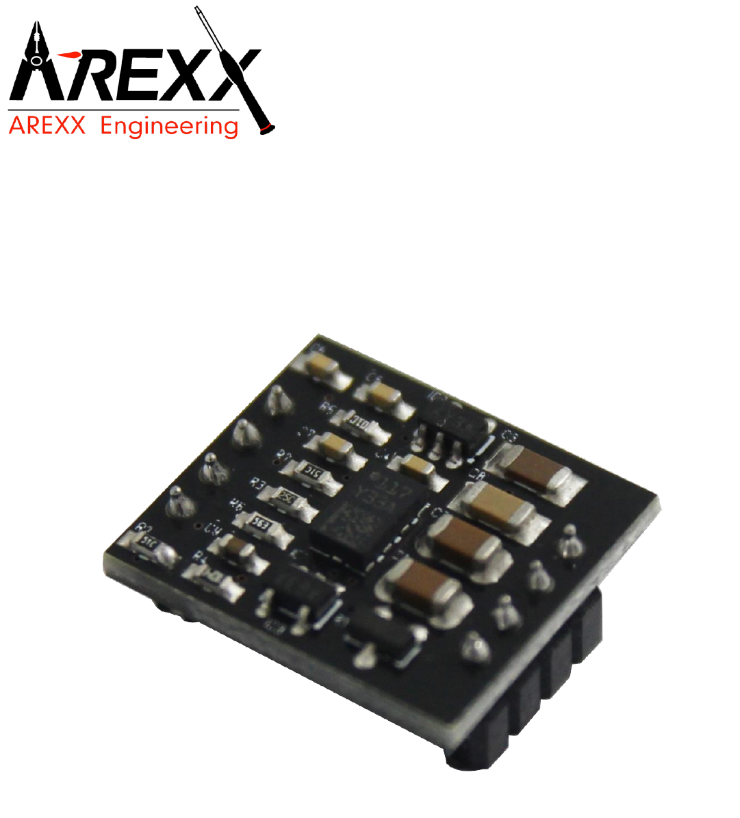
GYRO PCB LAYOUT