
Data Sheet

Application hints5
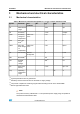
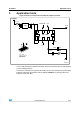
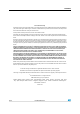
Figure 3: Electrical connections and external component values
100 nF
10kOhm470nF
Supply
C2
R1
C1
GND
1 µF
10nF
SLEEP/PD
GND
OUT Z
9
6
1
4
10 5
GND
ST
Vref
TOP VIEW
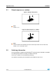
(TOP VIEW)
DIRECTION OF THE
DETECTABLE
ANGULAR RATE
+
z
LDO
2.2Ohm
GND
AM03841v1
Ω
Power supply decoupling capacitors should be placed in combination with an LDO regulator
(common design practice).
The device IC includes a PLL (phase-locked loop) circuit to synchronize driving and sensing
interfaces. Capacitors and resistor must be added at VCONT pin 3 (see figure above) to
implement a low-pass filter.
11/16DocID16568 Rev 2
Application hintsLY330ALH