
User manual

- 19 -
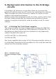
In the driver stage we may identify the DC-motor M. The
preamplier of the driver circuit is being simulated by resistor
R14. This resistor will pull the base-ports of transistors TR6
and TR5 to 0V, which results in a condition in which only the
right-sided branch is conducting a signicant current.
Transistors TR8, TR5 and TR9 are conducting and the other
transistors are blocked. As soon as we switch R14 to a positive
voltage the right-sided branch will be blocked and the motor
current will be reversed.
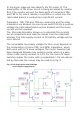
The Microcap Simulator allows us to calculate the currents
for all components and read the values from the schematic
window. The total supply current at 3V battery voltage will be
circa 300mA.
The remarkable low supply voltage for this circuit depends on
the combination of silicon PNP- and NPN- transistors, which
both work with 0.7V knee voltages. The motor however has
been designed between two collector ports, which in a satu-
ration mode merely conduct at 0.3V. For the motor M these
switches supply the motor with a respectable 1.5V. As calcula-
ted by Microcap the values may be read from g. 9.
.
Fig. 9: DC-settings for the H-Bridge
in the Hyper Peppy Robot