AREXX ARDUINO ROBOT AAR MANUAL: AAR-04 © AREXX - The Netherlands V062012 -1-
Contents 1. PRODUCT DESCRIPTION AAR 1.1 The ARDUINO Robotics Family 3 1.2 Specifications 3 2. ARDUINO General Description 5 3. AREXX ARDUINO ROBOT 10 3.1. Blockdiagram 10 3.2. AAR hardware 11 3.2. ARDUINO Software 12 4. The AREXX ARDUINO ROBOT (AAR) 13 4.1. Download and installation of the software 13 4.2. The Arduino language 13 4.3. Installation of a USB-driver 13 4.4. AAR Hardware 14 4.4.1. Installing the battery-compartment 14 4.5.
1. PRODUCT DESCRIPTION AAR 1.1. The ARDUINO Robotics Family Arduino is an open source-Platform for developing of electronic prototypes, which provides us with a microcontroller including all peripheral interfaces and the required software. The Arduino-concept has been designed to learn modern electronics for robotics, software control and sensors in the simplest possible way. As a successor for the ASURO-robot, which has been programmed in C-language we now designed the AREXX Arduino robot.
1.3. Precautions 1. Attention! You must read this manual before supplying power to any of the terminals! Incorrect connections may damage the hardware. 2. Attention! Please check the pin function diagram carefullyBe careful in wiring the circuitry. Incorrect connections may damage the modules. Respect the correct power supply’s polarity. A reversed power supply may damage the hardware. 3.
2. ARDUINO General Description 2.1. Who or what is ARDUINO? Arduino is an open source- single board microcontroller, which provides an easy access to programming, microcontrollers and projectplatforms for interactive objects for artists, designer, hobbyists and others. The Arduino-platform has been based on an Atmel’s ATmega168 or ATmega328 microcontroller.
2.2 Microcontrollers! 2.2.1. Applications A microcontroller (sometimes abbreviated µC, uC or MCU) is a small computer on a single integrated circuit containing a processor core, memory, and programmable input/output peripherals. Program memory and a small amount of data memory (RAM) is also often included on chip.
2.3. Power Consumption and Speed Some microcontrollers may operate at clock rate frequencies as low as 4 kHz, for low power consumption (milliwatts or microwatts). They will generally have the ability to retain functionality while waiting for an event such as a button press or other interrupt; power consumption while sleeping (CPU clock and most peripherals off) may be just nanowatts, making many of them well suited for long lasting battery applications.
Microcontrollers were originally programmed only in assembly language, but various high-level programming languages are now also in common use to target microcontrollers. These languages are either designed specially for the purpose, or versions of general purpose languages such as the C programming language. Microcontroller vendors often make tools freely available to make it easier to adopt their hardware.
In addition to the converters, many embedded microprocessors include a variety of timers as well. One of the most common types of timers is the Programmable Interval Timer (PIT). A PIT just counts down from some value to zero. Once it reaches zero, it sends an interrupt to the processor indicating that it has finished counting. This is useful for devices such as thermostats, which periodically test the temperature around them to see if they need to turn the air conditioner on, the heater on, etc.
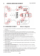
3. AREXX ARDUINO ROBOT 3.1 ARDUINO ROBOT Fig. :AAR PCB Block diagram 1. Connector plug for the battery compartment. (Be careful to check for the correct polarity!) 2. On/Off-Switch for the Robot. 3. Status-LED: signaling that the robot is being supplied from the power supply. 4. In case you are using rechargeable batteries you may interconnect this dual plug, which will supply the robot with the correct supply voltage 5. USB-connector to program the robot with the help of the Arduino-Software. 6.
3.2 Background-information for the AAR The front-side provides a USB-interface equipped with an FT232 IC. This chip transforms the USB-signal into a RS232 UART-signal, which may be processed by the ATMEGA328P Processor (located at right side of the front position). At the opposite side we positioned the ON/OFF-switch including a JP3-connector for the supply-connection and the motor-controller IC2.
3.3 BACKGROUND-INFORMATION FOR THE ARDUINO SOFTWARE Arduino Software belongs to the Open Source-category and is universally available to all, including the source codes for the programming platform. The Arduino programming platform has been equipped with a texteditor, a message window and a text-console. The programming platform may directly contact the AAR for communication and allows us to easily transfer programs into the processor.
4. Getting Started 4.1. Download and installation of Arduino’s Software Install the Arduino software (version 1) from the CD we are sure this will work. Later you also can go to the ARDUINO website and download the latest version from this site. IMPORTANT: using different versions of the ARDUINO Software and different version of the application software may give some problems. Somtimes with a new ARDUINO softtware update you have to modify your application software otherwise it wil not work! 4.2.
4.4. AAR hardware 4.4.1. Installing the batteries The robot has been designed for a power supply filled with four 1,5V AAA-cells. If you prefer to use rechargeable batteries the jumper JP4 should be installed as a bridge to prepare the system for a lower voltage of the rechargeable batteries (see fig. 1, number 4). ATTENTION! Installing the connecting jumper JP4 will disable the polarity check using the rectifier diode. Errors in power connections with installed jumper JP4 might seriously damage the robot.
4.5 ARDUINO software 4.5.1 Programming the Robot with Arduino Programs. Connect the robot by USB-cable to your PC. As soon as the robot has been connected to an USB-port the Arduino-system does not really need an extra battery or other power supply. Instead the USB-connection to the PC will provide the required power supply. ATTENTION: The robot will always be activated as soon as the system has been connected to the PC.
Fig. 4a Program Blink Fig. 4b Select Board At this stage we will have to select the correct Arduino-board at the menu-entryTools>Board> Arduino Duemilanove or Nano w/Atmega328 (see fig. 4b) 4.5.3 Select Compoort The next step defines the correct COM-port for the Arduino-interface. The correct COM-interface (or COM-port) for the robot is COM 12. In order to select the COM-interface please open the menu-entry: Tools>Serial Port>COM 12. (see fig. 5) Fig.
4.5.4. Program transfers from the PC to the Arduino Robot Please click the button, which has been marked with a red arrow (or alternatively follow the menu-entry „File>Uploading to I/O board“) to transfer the selected program to the connected Arduino-robot (see fig. 6a). The status window reports the compilation process of the program and as soon as the program successfully has completed the compilation the system will start the upload to the robot.
5. Background-information to the H-Bridge circuits A H-bridge is an electronic circuit which allows us to reverse the polarity of a device (such as a DC-motor) by controlling four switches. These H-bridges will often be found in robotics to control a motor rotation in two opposite directions. Modern systems use integrated circuits for motor control, but to learn the basic fundamentals and the dimensioning problems of power supplies it might be important to study an archaic circuit for motor controls. 5.
In the driver stage we may identify the DC-motor M. The preamplifier of the driver circuit is being simulated by resistor R14. This resistor will pull the base-ports of transistors TR6 and TR5 to 0V, which results in a condition in which only the right-sided branch is conducting a significant current. Transistors TR8, TR5 and TR9 are conducting and the other transistors are blocked. As soon as we switch R14 to a positive voltage the right-sided branch will be blocked and the motor current will be reversed.
The 3V-power supply is an ideal condition for a robot with a batterypack of only 2 cells. The PNP-transistors however cannot easily be integrated in an IC such as the L293D. An IC however has other advantages such as reliability, protection against bad circuitry and reduced PCB-area and low weight. For this reason we decided to use a L293D-chip with a dual H-bridge circuitry to simultaneously control two DC-motors. 5.2 A H-Bridge for 4,5 Volt The L293D-chip (see fig.
6. Odometry This chapter has been devoted to some interesting application-concepts for the AAR-robot. The ideas refer to studies and art-projects. Maybe developing such software will inspire us in programming micro-controllers. 6.1 Line-seekers, color-lovers and color-haters Light-sensitive sensors will allow us to program robots to behave like line-seekers, color-lovers or color-haters.
6.3 Complex Line-seekers Line-seeking and line-following robots usually will need a light source such as a LED and twi or more light sensors. These devices allow the system to identify a line and follow the track. Initially the robot may need a special search pattern routine to find a line. The pattern may consist of a strategy to follow a spiral pattern with a gradually increasing radius from the starting point.
Experienced programmers are aware of the complexity and design requirements of a program which needs to serve the problems of a line-follower with several differentiated color and sound dependencies. Programmers will have to design a program with a hierarchical set of numerous functions. The modular, structured concept will allow us to write a complex, but reliable software, which is performing the specified task.
7. Programming a Boot-loader ATTENTION! The described road-map in this chapter requires programming experience! You will be able to upload an Arduino-bootloader into the microcontroller: for instance with the help of STK500. In order to transfer any program, which has been written in Arduino language, into the Atmega micro-controller the Atmega-processor will have to be equipped with a special Arduino-boot-loader.
APENDIX - 25 -
Partlist Part C1 C2 C3 C4 C6 C7 C8 C9 C11 C12 C13 C14 C15 C16 C17 C19 D1 D2 IC1 IC2 IC3 IC4 IC5 JP1 JP2 JP3 JP4 JP5 SV2 T1 T2 T3 T4 U$1 U$2 U$3 U$4 X1 LED1 LED2 LED3 LED4 LED5 LED6 Value Package 18pF 18pF 0.
Part LED8 LED9 LED10 LED11 LED12 LED13 LED14 LED16 LED17 LED18 Q1 R1 R2 R3 R4 R5 R6 R7 R8 R9 R10 R11 R12 R13 R14 R15 R16 R17 R18 R19 R20 R21 R22 R23 R24 R25 R26 R27 R28 R29/C3 R31 R32 S1 S2 SV1 Value Package Rd Rd Rd Rd Gn Rd Bl Rd Rd Rd 16MHz 20k 20k 1k5 220 1k5 1k 680 680 20k 20k 220 220 10k 220 220 220 220 220 220
A.
B.
ATmega328P C.