Instruction Manual Specifications Length: Height: Main Rotor Diameter: Weight with Battery: Main Motor: Tail Motor: Battery: Charger: Transmitter: On-Board Electronics: 11.6 in (295mm) 4.3 in (110mm) 11.6 in (295mm) 3.2 oz (90g) N40 (installed) Micro-Coreless (installed) 500mAh 1S 3.7VLiPo (included) 1S 3.7V LiPo AC (included) 4-channel 2.
Table of Contents Specifications ........................................................................................................................................... 1 Introduction ............................................................................................................................................. 3 Safety Precautions and Warnings ............................................................................................................ 3 FCC Information ......................
Introduction When you’re ready to make the move from multi-rotor and coaxial to single-rotor heli flying there’s no better choice than the Ares™ [air-eez] Chronos FP 110. The advanced fixed-pitch and self-stabilizing rotor head design offers the agility and maneuverability of a single-rotor heli along with the stability of a coaxial heli so you can learn the basics of more advanced flying with confidence and in less time than ever before.
FCC Information This device complies with part 15 of the FCC rules. Operation is subject to the following two conditions: (1) This device may not cause harmful interference, and (2) this device must accept any interference received, including interference that may cause undesired operation. Caution: Changes or modifications not expressly approved by the party responsible for compliance could void the user’s authority to operate the equipment.
Required to Complete The Chronos FP 110 RTF includes everything needed to fly right out of the box. There’s nothing extra to buy or provide! Before the First Flight Checklist PLEASE NOTE: This checklist is NOT intended to replace the content included in this instruction manual. Although it can be used as a quick start guide, we strongly suggest reading through this manual completely before proceeding.
LiPo Battery Warnings and Usage Guidelines IMPORTANT NOTE: Lithium Polymer batteries are significantly more volatile than the alkaline, NiCd or NiMH batteries also used in RC applications. All instructions and warnings must be followed exactly to prevent property damage and/or personal injury as mishandling of LiPo batteries can result in fire. By handling, charging or using the included LiPo battery you assume all risks associated with LiPo batteries.
• Do not over-discharge the LiPo battery. Discharging the LiPo battery too low can cause damage to the battery resulting in reduced power, flight duration or failure of the battery entirely. LiPo cells should not be discharged to below 3.0V each under load. In the case of the 1-Cell/1S 3.7V LiPo battery used to power the Chronos FP 110, you will not want to allow the battery to fall below 3.0V during flight.
• When the battery is connected to the charger securely and with the proper polarity the LED indicator will glow solid red. The battery will be charging anytime the LED indicator is glowing solid red. • It will take approximately 1.0–1.5 hours to fully charge a mostly or fully discharged (not over-discharged) battery. And when the battery is fully charged the LED indicator will change to glow solid green.
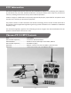
Installing Transmitter Batteries Install the six included AA batteries in the back of the transmitter by removing the screw securing the battery compartment cover/door then remove the battery compartment cover/door. Ensure proper polarity of the batteries before installing them as indicated by the markings molded into the battery compartment, then re-install the compartment cover/door and screw. Check for proper operation of the transmitter by switching the power switch ON (slide it upward).
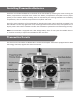
Proportional Mix Trimmer Knob The knob located near the top left-hand corner of the transmitter is used to adjust the amount of ‘mixing’ between the main and tail motors. Please see the ‘Proportional Mix Trimmer Knob’ section of this manual for more information. Dual Rate Button The button located near the top right-hand corner of the transmitter is used to toggle between the ‘Dual Rates’ available for the aileron and elevator controls/channels.
NOTE: All Chronos FP 110 helicopters are test-flown at the factory. And during each test flight the position/setting for the proportional mix trimmer knob is typically adjusted to provide very good trim and performance overall. However, it is possible for the position of the knob to change during handling of the transmitter so it may be necessary to adjust the position/setting of the knob to achieve the best possible trim and performance.
Flight Controls and Trimming In the event you are not familiar with the controls of the Chronos FP 110 please take the time to familiarize yourself with them as follows and before proceeding with your first flight: The left-hand stick on the transmitter controls both the throttle (climb/descend) and rudder (yaw left/right) channels. When the left-hand stick (also known as the ‘throttle’ stick) is in the lowest possible position the rotor blades will not spin.
The throttle trim lever (located immediately to the right of the left-hand/throttle stick) can be used to adjust the throttle control/channel output value for a given stick position. For example, raising the throttle trim will make it possible to maintain altitude with the helicopter when the left-hand/throttle stick is in a lower position. However, we do not typically recommend raising or lowering the throttle trim above/below the middle/centered position.
Moving the left-hand stick to the right will turn (yaw) the nose of the helicopter to the right about the axis of the main shaft. This is accomplished by increasing the speed/RPMs of the tail rotor. The rudder trim lever (located immediately below the left-hand stick) can be used to help keep the nose of the helicopter from turning (yawing) to the left or right when ‘hovering’ and without any left-hand stick/rudder control input.
The right-hand stick controls both the elevator (pitch fore/aft) and aileron (roll) channels. Pushing the stick forward will pitch the nose of the helicopter downward, allowing it to be flown forward. This is accomplished by having the elevator (right-hand) servo pull the swashplate downward. Pulling the right-hand stick backward will pitch the tail of the helicopter downward, allowing it to be flown backward. This is accomplished by having the elevator (right-hand) servo push the swashplate upward.
Moving the right-hand stick to the left will roll the helicopter to the left, allowing it to be flown to the left. This is accomplished by having the aileron (left-hand) servo pull the swashplate downward. Moving the right-hand stick to the right will roll the helicopter to the right, allowing it to be flown to the right. This is accomplished by having the aileron (left-hand) servo push the swashplate upward.
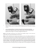
Installing and Removing the LiPo Flight Battery After the LiPo battery has been fully charged it’s ready to be installed in the helicopter. To install the battery in the helicopter start by removing the canopy. Next, with the wire leads and connector of the battery oriented so they point forward (away from the 4-in-1 control unit), place the battery in the battery holder so the hook-and-loop material on the battery and holder make contact.
• Before each flight you must ALWAYS turn the transmitter on BEFORE connecting the LiPo flight battery to the control unit. Never connect the battery to the control unit before powering the transmitter on first. And after each flight you should always disconnect the battery from the control unit before turning the transmitter off. • The left-hand/throttle stick must be set in the lowest possible position in order for the control unit to arm properly.
• AFTER INSTALLING THE BATTERY IN THE MOUNT/HELICOPTER YOU MUST BE CAREFUL TO ENSURE PROPER POLARITY BEFORE CONNECTING IT TO THE 4-IN-1 CONTROL UNIT. By orienting/aligning the wire leads of the battery and control unit so they’re ‘red to red’ and ‘black to black’ you’ll be able to make the connection with correct polarity.
In case the LED indicator does not glow solid red: • If the LED indicator continues to blink red slowly you do not have a positive RF link between the transmitter and receiver. First, check to be sure that the transmitter is powered on and that it has an adequate level of battery voltage/power. If the transmitter is already powered on, disconnect the battery from the control unit then turn the transmitter off.
Selecting a Flying Area Before proceeding with your first flights indoors or out please be sure to review the details in this section to ensure you’re choosing suitable spaces and conditions to achieve the best possible performance and flying experience. IMPORTANT NOTE: If you are a first-time or low-time pilot we strongly recommend allowing a more experienced pilot to test fly and properly trim the model before attempting your first flight.
Flying (General) Now that you’ve selected a suitable flying area you’re ready to fly! And when making your first flights we suggest following these steps: • Slowly raise the left-hand/throttle stick to increase the speed of the main rotor blades and until the model begins to lift off.
• When the helicopter is properly trimmed, maintain a stable hover and practice using the rudder, elevator and aileron controls to get a feel for how the helicopter responds to various control inputs. Remember to keep the control inputs as minimal as possible to prevent over-controlling the helicopter. • Continue to practice until you’re comfortable hovering the helicopter at approximately 20–24 inches of altitude.
Flying Outdoors The Chronos FP 110 is larger than other similar class models for improved visibility and performance when flying outdoors in winds up to 5-7 mph. Hints and Tips • Although the Chronos FP 110 can be flown successfully in winds up to 5-7 mph we do not recommend that all pilots fly in the wind, especially first-time and low-time FP heli pilots. This is because more experience is typically required to maneuver/fly the helicopter successfully in the wing.
Transmitter and Receiver Binding/Linking Binding/linking is the process of programming the receiver to recognize the Globally Unique Identifier (GUID) code of a single specific transmitter. These steps outline the binding/linking process of the M4LPH 4-Channel Helicopter Transmitter (AZSH1258) and receiver/control unit: • Provide power to the 4-in-1 control unit by connecting the flight battery. • If the receiver/control unit is not bound/linked to the transmitter the red LED indicator will blink slowly.
Notes ________________________________________________________________________________ ________________________________________________________________________________ ________________________________________________________________________________ ________________________________________________________________________________ ________________________________________________________________________________ ________________________________________________________________________________ ____________________
Replacement Parts List Item Number AZSH1254 AZSH1255 AZSH1256 AZSH1257L AZSH1257R AZSH1257AS AZSH1257GS AZSH1258MD2 AZSH1259 AZSH1260 AZSH1261 AZSH1262 AZSH1263 AZSH1264 AZSH1265 AZSH1266 AZSH1267 AZSH1268 AZSH1269 AZSH1270 AZSH1271 AZSH1272 AZSH1273 AZSH1274 Description 1-Cell/1S 3.7V LiPo, 0.5A 110-240V AC Charger: Chronos FP 110 500mAh 1-Cell/1S 3.7V 15C LiPo Battery, JST Connector: Chronos FP 110 4-in-1 Control Unit, Rx/ESCs/Mixer/Gyro: Chronos FP 110 1.7-Gram Digital Servo, Left: Chronos FP 110 1.
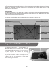
Exploded View # 13 14 15 16 17 18 19 20 21 22 23 24 25 26 27 28 29 30 31 32 33 34 35 36 37 38 39 40 41 42 43 44 45 46 47 48 49 Description (Total Quantity Used) M1.7x6mm Screw (12) Motor (1) M1.4x2.5mm Screw (5) Main Shaft Retaining Collar (1) Main Shaft (1) Feathering Spindle (1) Swashplate Assembly (1) Main Rotor Head/Hub (1) M1.7x6mm Screw (12) Main Rotor Blade Grip, Lower Part (2) M1.7x6mm Screw (12) Rotor Head Linkage, Long (2) Rotor Head Linkage, Short (2) Main Rotor Blade/Head Mixing Arm (2) M1.
Exploded View 30
Notes ________________________________________________________________________________ ________________________________________________________________________________ ________________________________________________________________________________ ________________________________________________________________________________ ________________________________________________________________________________ ________________________________________________________________________________ ____________________
Notes _________________________________________________________________________________ _________________________________________________________________________________ _________________________________________________________________________________ _________________________________________________________________________________ _________________________________________________________________________________ _________________________________________________________________________________ ______________
www.Ares-RC.com © 2013 Rev 06.30.