MegaVideo® Flex Installation Manual Models: 1.
MegaVideo® Flex Installation Manual Contents Package Contents ................................................................................................................................................... 3 Camera Overview.................................................................................................................................................... 6 Mounting the Sensor Unit ...........................................................................................................
MegaVideo® Flex Installation Manual CAUTION! 1. Do not attempt to service a damaged unit yourself. Refer all servicing to qualified service personnel. 2. Wiring methods shall be in accordance with the National Electrical Code/NFPA 70/ANSI, and with all local codes and authorities having jurisdiction. Wiring should be UL Listed and/or Recognized wire suitable for the application. 3. Always use hardware e.g. screws, anchors, bolts, locking nuts etc.
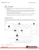
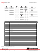
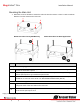
MegaVideo® Flex 8 Installation Manual 10 9 11 13 14 12 Reference # Description 1 1x Main Unit 2 2x Black Camera Fastening Nuts, 1x White Fastening Nut 3 1x Metal Sheet Bracket with Attached Plate 4 1x Sensor Unit 5 1x White Cover with Bubble 15 16 17 8 1x 5ft USB 2.0 to Micro USB 28/28 AWG, Shielded Twisted Pair Cable, No Active Repeater 1x 40ft USB 2.0 to Micro USB 28/24 AWG, Shielded Twisted Pair Cable, No Active Repeater 2x #6-32 1” Wood/ Metal Sheet Screw 9 4x #6-32 1.
MegaVideo® Flex Installation Manual 1x Mounting Template for Main Unit 1x Mounting Template for Sensor Unit 1x CD with Manual and Software NOTE: Make sure not to miss match sensor units and main units from different boxes if you are going to install more than one MegaVideo Flex camera.
MegaVideo® Flex Installation Manual Camera Overview The MegaVideo Flex is the only customizable discreet multi-megapixel camera on the market to provide interchangeable lens options with remote focus. The innovative design provides customers with the ability to add infrared illumination (sold separately) via two ports on the main unit. Flexible lens options include: 2.1mm, 2.8mm, 4mm, 6mm, 8mm, 12mm, and 16mm.
MegaVideo® Flex Installation Manual Mounting the Sensor Unit 1. Determine a secure location to mount the camera. 2. The camera can be mounted four ways: by cutting a hole and mounting the camera directly to a metal/wood surface or by using the supplied metal mounting bracket and attaching it to a metal/wood surface or via the ¼” 20 UNC thread, or via the MF-FMA flush mount bracket (sold separate). Choose the best method for your installation: a.
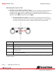
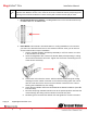
MegaVideo® Flex Installation Manual b. Mounting Camera Via Metal Bracket: This method is recommended if you want to minimize drilling holes into a surface. Follow the instructions in the table below: 10 8 9 Ref # Description 1/2 The metal sheet bracket plate (#1) and the metal sheet bracket base (#2) should already be attached. The bracket plate can be adjusted up or down with a Philips head screwdriver. 3 Attach one of the two camera fastening nuts along the front edge of the camera bubble.
MegaVideo® Flex 8/9/ 10 Installation Manual For Metal/Wood Sheet application: Prepare surface for installation. Thread a #6-32 Washer (#8) into each Machine Screw. Then, insert the 2x #6-32 1” Machine Screws (#10) through the opening of the metal sheet bracket. Fasten securely with a #6-32 Hex Nut (#9) on each. c. Directly Mount Sensor to Surface: The MegaVideo Flex can be mounted from the top or bottom via the ¼” 20 UNC thread. d.
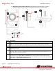
MegaVideo® Flex Installation Manual Mounting the Main Unit 1. Determine a secure location to mount the main unit from the camera. There is a 40ft. maximum distance from the camera to the main unit. Mount Procedure for Drywall/Masonry Ref # Mount Procedure for Metal Application Description For Drywall/ Masonry Applications 2 Prepare surface for installation by placing the main unit where desired and marking each of the four the holes with a pencil.
MegaVideo® Flex Installation Manual Connecting the Sensor, Main Unit and Optional IR NOTE: When connecting a sensor unit to a main unit, make sure the sensor and main unit are from the same box. The camera could be undiscoverable if you swap different sensor units on a main unit.
MegaVideo® Flex Installation Manual Reset to Factory Default 1. Press and hold the reset button (#5) for 10 seconds and release the reset button. The camera has been reset to the factory default. If the camera is not connected to DHCP server, the camera will use a Link-local address. 2.
MegaVideo® Flex Installation Manual Optional: Connecting Digital I/O To use digital I/O, connect digital I/O with pigtail cable connector on the main unit. Reference # Description 1 Input 2 Output NOTE: Camera supports digital input and digital output. See Table 1 for electrical characteristics. Electrical Characteristics Input Voltage (V) (Measured between + and – terminals) Output Current (mA) (Measured between + and – terminals) Applied Voltage Range: 0-80V MIN MAX ON 2.9 6.3 OFF 0 1.
MegaVideo® Flex Installation Manual Camera Power Up This product should be installed by a qualified service technician in accordance with the National Electrical Code (NEC 800 CEC Section 60) or applicable local code. 1. Connect the camera to a PoE port on 100Mbps network PoE switch using an Ethernet cable as shown in the image below. 2. If the camera is powered by an outside power supply, 12~48VDC or 24VAC, connect the power cable (Barrel Plug, 2.1mm I.D. x 5.5mm O.D. x 9.5mm).
MegaVideo® Flex Installation Manual NOTE: A yellow LED on the rear of the camera illuminates after a few seconds. The flashing yellow LED indicates that a link to your computer has been established. A green LED will blink when the camera has been accessed. NOTE: Wiring methods shall be in accordance with the National Electrical Code/NFPA 70/ANSI, and with all local codes and authorities having jurisdiction. Wiring should be UL Listed and/or Recognized wire suitable for the application.
MegaVideo® Flex Installation Manual Locally Storing Data The MegaVideo Flex includes a SDHC card slot for onboard storage. To set-up the SD card features, the Web Interface page or AV 200 can be used. The camera supports class 10 microSD or microSDHC cards up to 32GB. Not all SD cards are the same. Arecont Vision highly recommends using SanDisk Extreme Micro SD cards (or an equivalent substitute) as these cards have been fully tested without issue.
MegaVideo® Flex Installation Manual SD Card Set-up via Web Interface To set-up the SD card via the web interface, open your preferred web browser and type the camera’s IP address. NOTE: For supporting H.264 streaming on a webpage, the recommended browsers are Internet Explorer and Firefox. Scroll to the SD Card section as shown here: Select one of the recording methods: Continuous Recording to start continuously recording.
MegaVideo® Flex Installation Manual To playback recorded video: Input the date and time of the desired video (must be set between the Start and End time). Check the Playback SD card video checkbox to play the video. Playback tips: Video recorded to an SD card from an Arecont Vision camera can only be played back via an Arecont Vision camera that has the same or lower resolution. Playback can not be viewed with any other device.
MegaVideo® Flex Installation Manual SD Card Tab Menu Feature Description Playback Allows the user to choose the specific time of video to playback. Click to Play Button to play video specified in the Playback field. Continuous Recording Allows the user to continuously record without restriction. Default is unchecked box. Stop Continuous Recording AND Enable Event-triggered Recording Allows the user to enable events recording when network failure, motion alarm, or an I/O alarm is triggered.
MegaVideo® Flex Installation Manual SD Card Setup via AV200 To set-up the SD card via AV200, launch the AV200 application icon on the desktop. To enable recording to the SD card, select the desired camera and drag it to the workspace to open a view. From the window, select the SD card drop down menu. Choose: Continuous Recording - OR Event-triggered Recording to enable events recording for network failure, motion alarm or I/O alarm To launch the SD card playback window, click on the SD card icon.
MegaVideo® Flex Installation Manual Playback tips: Video recorded to an SD card from an Arecont Vision camera can only be played back via an Arecont Vision camera that has the same or lower resolution. Playback can not be viewed with any other device. For example, video recorded to an SD card via a 10MP camera can be played back on a 3MP camera but a 3MP can not be played back on a 10MP model. Page | 21 +1.818.937.0700 SD card must be inserted to any AV camera. support@arecontvision.com 877.CAMERA.
MegaVideo® Flex Installation Manual System Requirements Computer with Windows XP/Vista/7 operating system, network access, and Microsoft Internet Explorer web browser version 9.0 or later (32-bit). Camera Discovery, Setup, and Configuration For camera discovery and setup, the AV IP Utility is recommended. The software can be found on the CD included with your camera or at: http://www.arecontvision.com/softwares.php.
MegaVideo® Flex Installation Manual QoS – Quality of Service guarantees a certain level of a specified resource to selected traffic on a network. A QoS-aware network prioritizes network traffic and provides a greater network reliability by controlling the amount of bandwidth an application may use. IPv4 – The MicroDome G2 supports the IPv4 internet-layer protocol for packet-switched internetworking across multiple IP networks.
MegaVideo® Flex Installation Manual 3. Click the Full-range Focus button. The camera begins to autofocus with the lens stopping at the best overall point of focus. When the focus area turns to Green, the autofocus is complete. Refined Remote Focus 1. For a more refined, detailed focus, scroll to the Video Tab section and select the PTZ radial button. 2. Choose an area that has a lot of objects or an area you have an interest in seeing more details.
MegaVideo® Flex Installation Manual 5. Left click and drag to highlight the area within the zoomed window you created. 6. Click the focus menu, then the Short-Range Focus button. 7. The camera proceeds to go through the short range adjustment around the original focus. It stops at the best point of focus using the new reference area. When the box around the image illuminates green, the camera has completed the focus. For an additional focus, press the manual focus buttons (+20, +5, +1, -20, -5, -1). 8.
MegaVideo® Flex Installation Manual AV IP Utility Focus Tab Menu Page | 26 +1.818.937.0700 Feature Description Manual Focus: +20, +5, +1, 20, -5, -1 Numbers indicate the level of focusing in order to adjust the field-of-view. Full-range Focus Best for scenes that are completely out of focus. The camera automatically scans the full focus range of the scene to find the best focus position. Short-range Focus Best for scenes that are slightly of out of focus.
MegaVideo® Flex Installation Manual Mounting Templates mm/inches Page | 27 +1.818.937.0700 support@arecontvision.com 877.CAMERA.8 www.arecontvision.com avsales@arecontvision.
MegaVideo® Flex Installation Manual mm/inches Page | 28 +1.818.937.0700 support@arecontvision.com 877.CAMERA.8 www.arecontvision.com avsales@arecontvision.
MegaVideo® Flex Installation Manual Support 1. Arecont Vision FAQ Page Located at ArecontVision.com 2. Check the following before you call: Restore camera to factory default with AV200 or the camera webpage. Upgrade to the latest firmware by visiting ArecontVision.com. Isolate the camera on a dedicated network and test with AV200. Swap the “troubled” camera with a known good camera to see if the problem follows the camera or stays at the location. 3.