SurroundVideo® Omni SX Installation Manual Models: 12 Megapixel • AV12975DN-NL • AV12975DN-28 • AV12975DN-08 • AV12976DN-NL • AV12976DN-28 • AV12976DN-08 20 Megapixel • AV20975DN-NL • AV20975DN-28 • AV20975DN-08
SurroundVideo® Omni SX Installation Manual Contents Package Contents ................................................................................................................................................... 3 In-ceiling Mount ..................................................................................................................................................... 10 Pendant Mount ...........................................................................................................
SurroundVideo® Omni SX Installation Manual CAUTION! 1. Do not attempt to service a damaged unit yourself. Refer all servicing to qualified service personnel. 2. Wiring methods shall be in accordance with the National Electrical Code/NFPA 70/ANSI, and with all local codes and authorities having jurisdiction. Wiring should be UL Listed and/or Recognized wire suitable for the application. 3. Always use hardware e.g. screws, anchors, bolts, locking nuts etc.
SurroundVideo® Omni SX Installation Manual Warranty Information Global (3 Year) Limited Warranty ARECONT VISION COSTAR warrants to Purchaser (and only Purchaser) (the “Limited Warranty”), that: (a) each Product shall be free from material defects in material and workmanship for a period of thirty-six (36) months from the date of shipment (the “Warranty Period”); (b) during the Warranty Period, the Products will materially conform with the specification in the applicable documentation; (c) all licensed pro
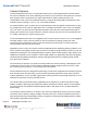
SurroundVideo® Omni SX Installation Manual Camera Overview The SurroundVideo® Omni SX, next generation multi-sensor, multi-megapixel dome camera pushes the ease of installation even further providing users with four (4) remote focus lens options on a unique 360° magnetic track encompassed in a single indoor/outdoor, impact-resistant housing. The customization of this camera is unparalleled offering a range of interchangeable lens options for each individual sensor including 2.1, 2.
SurroundVideo® Omni SX Installation Manual Installation 1. Determine a secure location to mount the camera. 2. Use the supplied security L-key, to loosen the four (4) screws securing the dome cover. 3. Remove the dome cover and protective foam. Do not remove screws from the dome cover. The SurroundVideo® Omni SX camera has been designed to provide installers with flexible mounting options such as ceilings, walls, poles or corners.
SurroundVideo® Omni SX Installation Manual Ensure you have the proper compatible mounting parts prior to starting your installation: Pendant mount Reference # 1 2 3 Pendant Mount Components Required Pendant mount (AV-PMJB-W) with integrated junction box SurroundVideo® Omni SX camera SO-CAP-W mounting cap Wall mount Reference # 1 2 3 Page | 7 +1.818.937.
SurroundVideo® Omni SX Installation Manual Pole mount Reference # 1 2 3 4 Mount Type Pole mount Pole Mount Components Required AV-WMJB-W wall mount SO-CAP-W mount cap SurroundVideo® Omni SX camera AV-PMA-W pole mount adapter Corner mount Reference # 1 2 3 4 Page | 8 +1.818.937.0700 Mount Type Corner mount Corner Mount Components Required AV-WMJB-W wall mount SO-CAP-W mount cap SurroundVideo® Omni SX camera AV-CRMA-W corner mount adapter support@arecontvision.com 877.CAMERA.8 www.arecontvision.
SurroundVideo® Omni SX Reference # 1 2 Installation Manual Mount Type In-ceiling mount In-ceiling Mount Components Required SO-FMA in-ceiling adapter SurroundVideo® Omni SX camera NOTE: It is recommended to conduct periodic inspections of the installation. Rust on the metal parts or screws may result in damage to the camera. 4. Use the Arecont Vision software AV IP Utility located on the CD or available for download at our website (www.arecontvision.
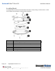
SurroundVideo® Omni SX Installation Manual In-ceiling Mount To properly flush mount the SurroundVideo® Omni SX to a drop ceiling or similar surface, a flush mount adapter kit (SO-FMA) is required (sold separately). Reference # 1 2 3 4 5 6 7 Page | 10 +1.818.937.0700 Description SO-FMA flange plate support arm SO-FMA flush mount bracket assembly Lever screw SurroundVideo Omni SX camera Bubble (without gasket) SO-FMA trim ring Trim ring screws support@arecontvision.com 877.CAMERA.8 www.arecontvision.
SurroundVideo® Omni SX Installation Manual 1. Cut a 9” diameter hole in the ceiling using the template provided. 9” 2. Remove existing Dome cover from Omni SX camera and remove gasket from Bubble. 3. Attach Flush mount bracket assembly to Omni SX camera as shown and fasten a safety cable to one of the 3 holes in the bracket assembly. (Cable not supplied.) 4. Insert housing assembly into ceiling hole and tighten the lever screws until the flush mount is snuggly installed.
SurroundVideo® Omni SX Installation Manual 5. Snap bubble (without gasket) into flush mount trim ring and attach the trim ring to the flush mount adapter by rotating until it magnetically snaps in place then tighten the trim ring screws. 6. To configure the camera, reference the set-up section. Pendant Mount For a proper pendant mount installation, the AV-PMJB-W pendant mount and SO-CAP-W mount cap are required (sold separately).
SurroundVideo® Omni SX Installation Manual Figure 2: Attach the camera to the SO-CAP-W with the supplied screws 5. To configure the camera, reference the camera discovery, set-up and configuration section. Page | 13 +1.818.937.0700 support@arecontvision.com 877.CAMERA.8 www.arecontvision.com avsales@arecontvision.
SurroundVideo® Omni SX Installation Manual Surface Mount The SurroundVideo® Omni SX can be directly attached onto hard ceilings or walls including wood, plastic, metal and concrete. 1. Use the template, anchors, and screws provided to prepare the mounting provisions for the camera installation. 2. Use the supplied security L-key, to loosen the four (4) tamper resistant screws securing the dome cover. Do not remove screws from the dome cover.
SurroundVideo® Omni SX Installation Manual 3. Remove the dome cover and set aside. Remove the protective foam and discard. 4. If mounting the camera outside or in a wet environment, thread the camera cable through the hole on the supplied rubber gasket and align with the three holes on the top of the housing. Ensure the gasket is properly seated flush with the camera housing.
SurroundVideo® Omni SX Installation Manual Reference # 1 Description Install 3 supplied dry wall anchors using the supplied mounting template 2 Attach supplied (optional) tether plate Attach supplied rubber gasket to the camera housing by threading the camera cable through the hole in the gasket (ensure the gasket is seated properly) Align 3 supplied screws with the dry wall anchors and screw camera into place 3 4 5 Attach the dome cover, ensuring the rubber gasket is properly seated, with the tamper
SurroundVideo® Omni SX Installation Manual Wall Mount For a proper wall mount installation, the AV-WMJB-W wall mount and SO-CAP-W wall mount cap are required (sold separately). A wall mount should only be attached onto hard ceilings including wood, plastic, metal, and concrete. 1. Using the Mounting template, prepare the mounting provisions for the camera installation. 2. Connect wall mount cap and wall mount as shown in Figure 1.
SurroundVideo® Omni SX Installation Manual Pole Mount For a pole mount installation, the AV-WMJB-W wall mount, AV-PMA-W pole mount, and SO-CAP-W mount cap are required (sold separately). A pole mount should only be attached onto hard ceilings including wood, plastic, metal, and concrete. 1. 2. 3. 4. Using the mounting template, prepare the mounting provisions for the camera installation. Connect the wall mount cap and wall mount.
SurroundVideo® Omni SX Installation Manual Figure 2: Attach wall mount adapter to pole mount adapter Reference # Description 1 Steel straps with compression screws AV-WMJB-W wall mount 2 SO-CAP-W mount cap 3 Conduit 4 AV-PMA-W pole mount 5 AV-JBA-W Junction box 6 Apply Teflon water seal tape to the thread of ¾” NPT pipe to avoid water leakage 7 7. Use the supplied two Steel Straps to attach the Pole Mount Adapter to the pole and tighten the compression screws as shown in Figure 2. 8.
SurroundVideo® Omni SX Installation Manual Corner Mount For a corner mount installation, the AV-WMJB-W wall mount, AV-CRMA-W corner mount, and SOCAP-W mount cap are required (sold separately). A corner mount should only be attached onto hard corner surfaces including wood, plastic, metal, and concrete. 1. 2. 3. 4. Using the Mounting template, prepare the mounting provisions for the camera installation. Connect the wall mount cap and wall mount.
SurroundVideo® Omni SX Installation Manual Figure 2: Attach corner mount adapter to exterior corner wall Reference # Description 1 Attach corner mount adapter to exterior 90° corner wall AV-WMJB-W wall mount 2 SO-CAP-W mount cap 3 Conduit 4 AV-CRMA-W corner mount adapter 5 AV-JBA-W Junction box 6 Apply Teflon water seal tape to the thread of ¾” NPT pipe to avoid water leakage 7 7. Using the screws provided (or other hardware), attach the Corner Mount Adapter to an exterior 90° corner wall.
SurroundVideo® Omni SX Installation Manual Electrical Box Adapter The AV-EBAR-W electrical box adapter is used to attach the camera to a common single, double or square electrical box. 1. Using the AV-EBAR-W’s supplied machine screws, match the mounting holes on the adapter with the threaded holes on the electrical box. Ensure every threaded hole is matched with a mounting hole. 2. Attach the electrical box adapter to the user supplied electrical box.
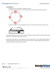
SurroundVideo® Omni SX Installation Manual Setting up the Cameras The SurroundVideo® Omni SX is user configurable. Prior to installing the camera, thought should be given to the sensor positions. It is always easier to make adjustments before the camera is installed. The camera lenses are shipped in a 360º position as shown below (Figure 2). To customize the sensors, simply remove the two screws for each individual sensor, position anywhere on the magnetic track and then screw into place.
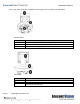
SurroundVideo® Omni SX Installation Manual Reference # 1 Description 180° configuration 2 Random configuration 3 270º configuration 4 Assembly line configuration 5 Random configuration Page | 24 +1.818.937.0700 support@arecontvision.com 877.CAMERA.8 www.arecontvision.com avsales@arecontvision.
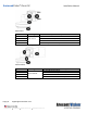
SurroundVideo® Omni SX Installation Manual Aligning the Cameras Properly aligning each camera is essential during setup. Each camera must be placed in a counterclockwise sequence on the circumference of the track to ensure proper viewing of each camera.
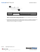
SurroundVideo® Omni SX Installation Manual Adjusting the Pan, Tilt and Focus 1. Remove the dome cover by loosening the captive fasteners with the supplied Philips head screwdriver. 2. Power on the camera to adjust the pan, tilt and focus. 3. Adjust the pan and tilt to obtain the desired field of view. Then, lock the camera head in place by tightening at least two of the three set-screws with the supplied flat-head screwdriver (Figure 1). Do not over torque the screws.
SurroundVideo® Omni SX Installation Manual NOTE: Positioning the lens motor to close to the board may cause interference with the magnetic Omni track. Ensure each lens motor is positioned away from the board. Incorrect Correct Changing the Lens 1. Remove the dome cover by loosening the captive fasteners with the supplied L-key. 2. Loosen the lens lock screws (3) using the supplied flat-head screwdriver (if necessary). Only do so if the lens seems very tight when turning. 3.
SurroundVideo® Omni SX Installation Manual Auxiliary I/O Functions The auxiliary input and output are accessible from the back panel, as shown in Figure 1. OUT+ OUT- IN+ IN- GND Figure 1 The output consists of an optically coupled solid state relay (SSR) and the input has an optocoupler. Both the SSR and optocoupler have an isolation voltage of 1500 VRMS between the external terminals and internal camera circuitry. The input is further protected with a serial 250Ω resistor and a debouncing circuit.
SurroundVideo® Omni SX Installation Manual OUTPUT Relay Control and Function The camera has an output for activating an external device. The camera supports both transient and continuous relay operation. You can operate the relay during an active connection using the API command set. Typical applications include turning on lights or activating doors and locks.
SurroundVideo® Omni SX Installation Manual INPUT Alarm Control and Detection The input optocoupler supports two ways to connect external unsupervised alarms to Arecont Vision camera. Only one of the following two schemes should be used at any given time. OPTION-1: UNSUPERVISED ALARM DETECTION In this scheme the IN+ & IN- terminals can be used for external signaling devices, such as door contacts or motion detectors.
SurroundVideo® Omni SX Installation Manual OPTION-2: INPUT VOLTAGE DETECTION In this scheme the IN- & GND terminals can be tied to an external power source. The camera can detect a range of voltage to trigger an internal alarm on|off condition.
SurroundVideo® Omni SX Installation Manual Camera Power Up This product should be installed by a qualified service technician in accordance with the National Electrical Code (NEC 800 CEC Section 60) or applicable local code. Make sure that your installation of wires complies with Electrical Code of the local government where the camera is installed and no bare wires are exposed. 1. Connect the camera to a PoE port on 100Mbps network PoE switch using an Ethernet cable as shown in the image below.
SurroundVideo® Omni SX Installation Manual CAUTION! Make the connections inside a watertight compartment. Isolate unused power wires individually. After connections are made, ensure that the watertight compartment is tightly closed and cables and conduits are properly sealed to prevent ingress of water. 3. Connect the PoE switch to your computer’s network port using an Ethernet cable. NOTE: A yellow LED on the rear of the camera illuminates after a few seconds.
SurroundVideo® Omni SX Installation Manual System Requirements Computer with Windows XP/Vista/7 operating system, network access, and Microsoft Internet Explorer web browser version 9.0 or later (32-bit). Camera Discovery, Setup, and Configuration For camera discovery and setup, the AV IP Utility is recommended. The software can be found on the CD included with your camera or at: http://www.arecontvision.com/softwares.php.
SurroundVideo® Omni SX Installation Manual QoS – Quality of Service guarantees a certain level of a specified resource to selected traffic on a network. A QoS-aware network prioritizes network traffic and provides a greater network reliability by controlling the amount of bandwidth an application may use. IPv4 – This camera supports the IPv4 internet-layer protocol for packet-switched internetworking across multiple IP networks.
SurroundVideo® Omni SX Installation Manual 3. Click the “Select Channel” and choose channel 1. 4. Click the Full-range Focus button. The camera begins to autofocus with the lens stopping at the best overall point of focus. 5. Please complete the same action for Channel 2, 3, and 4 by following steps 2 to 5. Page | 36 +1.818.937.0700 support@arecontvision.com 877.CAMERA.8 www.arecontvision.com avsales@arecontvision.
SurroundVideo® Omni SX Installation Manual AV IP Utility Focus Tab Menu Page | 37 +1.818.937.0700 Feature Description Select Channel Allows user to change settings of each channel. All the parameter settings in “Settings” Menu only apply to the selected channel. Manual Focus: +20, +5, +1, 20, -5, -1 Numbers indicate the level of focusing in order to adjust the field-ofview. Full-range Focus Best for scenes that are completely out of focus.
SurroundVideo® Omni SX Installation Manual Troubleshooting Before troubleshooting, visit http://www.arecontvision.com/ to ensure your camera has the most current firmware version. Problem Possible Cause • Reflection on the image Day/Night switch failure or image quality problem Page | 38 +1.818.937.0700 • Lens faces the bubble’s crease. The angle between the lens and bubble are not perpendicular. The lens motor positioned to close to the board may cause interference. support@arecontvision.
SurroundVideo® Omni SX Installation Manual SurroundVideo Omni Mounting Template Page | 39 +1.818.937.0700 support@arecontvision.com 877.CAMERA.8 www.arecontvision.com avsales@arecontvision.
SurroundVideo® Omni SX Installation Manual Support 1. Arecont Vision FAQ Page Located at ArecontVision.com 2. Check the following before you call: • Restore camera to factory default with AV IP Utility or the camera webpage. • Upgrade to the latest firmware by visiting ArecontVision.com. • Isolate the camera on a dedicated network and test with AV IP Utility. • Swap the “troubled” camera with a known good camera to see if the problem follows the camera or stays at the location. 3.