
User manual


33 User Manual
Arduino Materia 101
parameters. Depending on the parameters
and the shape of the model, and then create
support structures read, so having a filament
support. At the end of printing, with some
patience, you remove these structures and
the piece remains clean and with the shapes
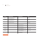
you want. Here is an example of an object
that requires the supports accompanied by
the G-Code generated with these supports.
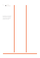
The supports are vertical structures under
the cheekbones and inside of the orbits.
The supports are vertical structures under
the cheekbones and inside of the orbits.
Keep in mind that the surfaces of contact
between support and model we will have
a very low surface finish for the concrete
possibility that the two areas are merged
together: this will require a finishing to
remove the backing material and arrange
some finishes (if deemed necessary).
In professional printers supports
are manufactured using special
thermoplastic, possible to dissolve
through special chemical or thermal
baths, filed with a second extruder.
PRINTING DETAILS
When you print a piece, you define the
various parameters including the thickness of
the layer. This value has a significant impact
on the definition of the object for all surfaces
that grow upward with an inclination much
bland. lmmaginate an inclined plane and
mentally slice it: the size of the slices can
vary a lot and, if they are drawn with a fixed-
width line, you can open the spaces between
one layer and the next. If the number of
slices increases because they are thinner, the
spaces between and the next. If the number
of slices increases because they are thinner,
the spaces between a and the next layer is
reduced so the shape is better defined under
the horizontal profile, both in the vertical
one. For this reason also the z-axis resolution
is hyped as a distinctive element of 3D
printers.
A side effect of layer thickness prints motto
bass (from 0.1 to 0.2 mm) is increasing
the printing time: the track will be built
with the same amount of material, but the
extruder will have take much more “Street”
because of the greater number of layers to
be created, even if each is made with less
material, and then the total does not change.
Each type of object has its own range of
optimum thickness for printing and only
with a bit of experience you can intervene on
this knowing what parameter are you going
to actually meeting. Our tip is to choose
a small enough, but with an articulated
form, upon which to pursue a systematic
experimentation, thanks to which you will be
able to see the effect of each variation.
The definition on the two axes X and Y it is
not controllable by the user resulting from
the model geometry, being composed of
triangles, could show the facets in place
of soft surfaces, rounded or well detailed.
This depends on the number of triangles
in the mesh of the components. More
triangles can bring greater detail, or are
simply the consequence of a process
of creating non-optimized mesh.
The number of triangles determines a
greater job for the slicing software and if the
triangles are tens of thousands, then they can
even cause processing problems. As you can
guess, below a certain threshold the details
are no longer “resolved” from the printer
and then are basically useless. Or, rather, are
significant in view of the enlargement of the
model for printing a detail. To reduce the
number of triangles describing the 3D model
there are several programs and even Slic3r
himself provides an option that allows you
to define under which size details go ignored,
simplifying and speeding up the model
slicing.
Fig. 3 Fig. 4