
User manual


20 User Manual
Arduino Materia 101
CALIBRATION
The steps in the installation manual chapter
3e, figures 14 and 15, consists in printing
of rectangles made with one layer on top,
allowing you to assess the adhesion of the
material to the print and to figure out if
the plan is leveled properly observing the
extrusion width must be equal at all points
of the perimeter. A tight stretch indicates
greater distance between printing bed and
extruder (plan too low), while a sudden large
and discolored indicates a plane too high.
Going to touch the tip of the screwdriver
wrench strokes closer, you’ll notice that is
a departure from the press: this is a further
sign of a flat area that is too low.
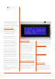
This procedure provides for an input
in the function, when on the display
you will read “even Z- plane” when the
extruder is 230° starts the first rectangle.
Considering the result you can intervene
on the four screws at the corners and,
after the adjustments, press on the knob
to verify the result through the tracking
of a second rectangle. After this round of
tinkering, the machine draws a circle in the
center of the rectangle to test the result.
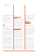
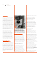
REGULATING FINAL
LEG OF AXIS Z
There is also, for subsequent regulations that
require only a rapprochement or removal of
the nozzle, the ability to adjust the Z limit,
running ahead or by delaying it. To adjust the
limit switch intervention Z let’s turn the black
knob on bottom of machine (see picture);
clockwise increase the distance plate-nozzle
going to decrease the total travel of Z, while
turning it counterclockwise decrease the
distance plate-nozzle, lengthening the total
travel of Z.
Sulla vostra Arduino Materia 101 vi
consigliamo di avere sempre almeno un
centimetro di filetto della manopola
avvitato come in Fig. 3 (vedi capitolo 3e
figure 7 e 8 del manuale di assemblaggio).
Calibrating axes X and Y
If printing your objects you find that the
circles are not exactly round or that the
joints, despite the necessary CAD drawn,
tolerances don’t fit together properly, it is
probably necessary to calibrate the X and
Y axes on your printer. The possible X and
Y calibrations on your Arduino Materia 101
are of two types, software or hardware:
— Recovering of scraps and usage
of M99 (software calibration)
If you have a scrap on a strap of one of
the two axes you will recognize it by
checking any hole or circle printed.
Recognize the direction of the scrap, for
example, if the flat part appears along the
X axis (towards the front of the printer and
printer), as shown in the figure above, it
means that you have a game on the Y-axis.
The first intervention is checking the
tension of the belts on the axis with
the game, after that you can act via
software to correct the same.
In the start g-code of Slic3r or slicing
software used enter the command M99
Y0 Y0 .2 .2, where stands for the game
away to retrieve. You can enter the value
and use the TEST from our downloadable
gcode website to check the correct
value to be inserted to make the game
on the axis vanishes permanently.
— Squaring off axes X and Y
(hardware calibration)
If your circles are ovoid or teams of the
blocks (figure below) are not “squared”
maybe you need to realign the print deck.
To verify that the X and Y axes are among
their orthogonal, we can always use the file
test. Gcode downloadable from our website,
which also contains the printing of some
rectangles. Now measure the two diagonals
of a rectangle printed: if they are together
again we’ll have to go to work to put
together the X and Y axes.
This procedure requires a certain dexterity
and experience on machine: If you’re not sure
about it we suggest you avoid it.
Prepare menu, select “Auto Home”;
Now let us relieve the bugle that screw the
strap on the left shoulder of the machine;
at this point we slide a single tooth belt
over his shoulder forward or backwards to
correct the detected square; ritensioniamo
the belt and repeat the test print.
See Chapter 7, image 17 of the Assembly
Manual for the squaring procedure.
Fig. 3