
User manual


32 User Manual
Arduino Materia 101
attention and has a critical point can still
become a print with a guaranteed result.
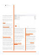
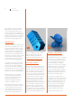
The support is generated by the slicing
software if it is enabled at the creation of
the print parameters. Depending on the
parameters and the shape of the model, you
can create a support structure. At the end
of printing, with some patience, you remove
these structures and the piece remains
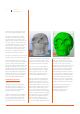
clean and has the shape you wanted. Here
is an example of an object that requires
the supports accompanied by the G-code
and is generated with these supports.
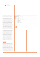
The supports are vertical structures under the
cheekbones and on the inside of the orbits.
Keep in mind that the surfaces of contact
between the support and the model will have
a very low surface finish to make certain
that the two areas are merged together. This
will require a finishing touch to remove the
backing material and create a finished look (if
deemed necessary). In professional printers,
supports are manufactured using special
thermoplastic made by a second extruder.
Later, these supports are dissolved with a
special chemical or with thermal baths.
PRINTING DETAILS
When you prepare an object for
printing, you define various parameters
including the thickness of each layer.
This value has a significant impact on the
resolution of the object for all surfaces
that grow upwards at an angle.
Imagine an inclined plane and mentally slice
it. The size of the slices can vary a lot and
if they are drawn with a fixed line width,
you can open the spaces between one
layer and the next. If the number of slices
increase, they are thinner so the inclination
is defined in a smoother manner. For this
reason also, the Z-axis resolution is spoken
of as the main resolution of 3D printers.
A side effect of a thinner layer height is
that it takes greater amounts of time. In
other words, a greater amount of layers
to print equals more area to cover. On
the other hand, the quality is going to be
better and layers might bond better.
Each type of object has its own range of
optimum thickness for printing and you
will learn how this parameter interacts
with the object. A tip is to choose a small
but articulated shape that you can pursue
with systematic experimentation. Practice
with this and you will be able to see the
effect of each variation. The definition on
the two axes, X and Y, it is not controllable
by the user. This is a product of the model’s
geometry, which is composed of triangles.
If the amount of triangles describing a
circle is low, that could show facets in
place of soft surfaces and well rounded
curves. More triangles bring greater detail.
A larger amount of triangles means a
larger job for the slicing software and if
the triangles are in the tens of thousands,
then they can even cause processing
problems. As you can guess, above a certain
level the details are no longer recreated
by the printer and then they are basically
useless. Or, rather, are only significant
when blowing up the detail of a model. To
reduce the number of triangles describing
the 3D model, there are several programs
and even Slic3r itself provides an option. It
that allows you to define a size threshold
for details to go ignored or simplifying and
this will speed up the slicing of the model.
It should be also considered that the
recommended minimum thickness
of the walls is 1.05 mm on the
vertical axes, consisting of three
lines of plastic (perimeters).
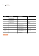
Fig. 3 Fig. 4