
User manual


20 User Manual
Arduino Materia 101
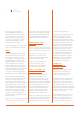
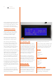
ADJUSTING THE AXIS
Z ENDSTOP
There is a way of adjusting the overall
distance from the nozzle to the print
surface. To do this, adjust the Z axis “end-
stop” (a simple on-off switch). Turn the
black knob in the back of the machine (see
picture); clockwise to increase the distance
and counterclockwise to decrease the
distance between the surface and nozzle.
On your Arduino Matter 101, it is recommend
that you always have at least one
inch of space on the z-axis adjustment bolt
available, as seen in Fig . 3 (see section 3e
Figures 7 and 8 of the assembly manual).
CALIBRATING THE
X & Y AXIS
There is also, for subsequent regulations that
require only a rapprochement or removal of
the nozzle, the ability to adjust the Z limit,
running ahead or by delaying it. To adjust
the limit switch intervention Z let’s turn
the black knob on bottom of machine (see
picture); clockwise increase the distance
plate-nozzle going to decrease the total
travel of Z, while turning it counterclockwise
decrease the distance plate-nozzle,
lengthening the total travel of Z.
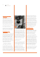
— Compensation for backlash and
usage of M99 (software calibration)
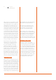
If you have backlash on the Y or X axis,
you will notice it by looking at any hole or
circle you print. Notice the direction of the
backlash, for example, if the circle appears to
be flatter on the X axis (towards the front of
the printer), as shown in the figure above, it
means that you have backlash on the Y-axis.
The first intervention is to check the tension
of the belts on the axis with the backlash,
after that you can use software to correct
the error. In the start of G-code of Slic3r or
the slicing software being used, enter the
command: M99 X0 Y0.2 Z0 E0, where “Y0.2”
stands for the backlash to be compensated
for on the Y-axis. “0.2” stands for 0.2 mm.
Enter the value and use the Materia101_test_
print.zip from our support site to see if the
value inserted is the correct one to remove
the backlash from the axis permanently.
— Squaring off axes X and Y
(hardware calibration)
If your circles are ovals, groups of boxes are
not square or if the infill of the boxes are
not connecting with the outer shell, maybe
you need to realign the X and Y axes.
To verify that the X and Y axes are
perpendicular, you can use the file
“Materia101_test_print.zip”, downloadable
from our website, which contains a print
of two boxes. After you are done printing
the test, measure the two perpendicular
sides of one of the printed boxes: if they are
still incorrect (not the same length or not
perpendicular) you will have to recalibrate
the X and Y axes. This procedure requires
a certain dexterity and experience on the
machine: If you are not sure about it, avoid
it. Go to the Prepare menu, select “Auto
Home”; Now unscrew the bolt that tightens
the strap on the left shoulder of the machine.
Then slide a single tooth of the belt over
through the shoulder, forwards or backwards,
to correct for un-squareness of the axis;
tighten the belt and repeat the test print.
See Chapter 7, image 17 of the Assembly
Manual for the squaring procedure.
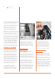
TIGHTENING THE
EXTRUDER SPRINGS
Your Arduino Materia 101 is equipped with a
spring suspended idler. This solution allows
the extruder to compensate for thickness
variations in the filament and give the
same amount of pressure all the time.
The correct pressure from the idler allows
for optimum feeding of the filament to the
extruder. To check if the tension on the springs
are correct, enter the “Prepare” menu and
choose the option “Change filament”. Wait
until the machines ejection cycle is done and
insert the filament. While loading, hold the
filament thread with your fingers and try and
keep it from being pulled into the extruder. If
there is a “slip” of the drive gear (the sprocket
doing the pulling), tighten the springs until
you hear a sound like a “tak tak tak”. This
means that the tension is high enough.
At the same time, the tension on the springs
can not be too high. This is to protect the
motor when it is under stress and reduce
the the risk of the motor losing steps.
Fig. 3