
Reference Manual

Arduino® Portenta Vision Shield LoRa®
11 / 18 Arduino® Portenta Vision Shield LoRa® Modified: 16/08/2022
5 Connector Pinouts
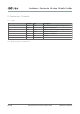
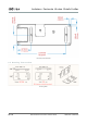
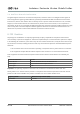
5.1 JTAG
Pin Function Type Description
1 VDDIO Power Positive Reference voltage for debug interface
2 SWD I/O Single Wire Debug Data
3,5,9 GND Power Negative reference voltage for debug interface
4 SCK Output Single Wire Debug Clock
6 SWO I/O Single Wire Debug Trace
10 RESET Input CPU Reset
7,11,12,13,14,15,17,18,19,20 NC Not Connected
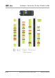
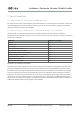
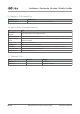
5.2 High Density Connector