
Reference Manual

Arduino® Nano RP2040 Connect
15 / 19 Arduino® Nano RP2040 Connect Modified: 12/07/2022
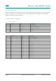
5.3 JP2
Pin Function Type Description
1 D13 Digital Digital Pin 13
2 3.3V Power 3.3V Power
3 REF Analog NC
4 A0 Analog Analog Pin 0
5 A1 Analog Analog Pin 1
6 A2 Analog Analog Pin 2
7 A3 Analog Analog Pin 3
8 A4 Analog Analog Pin 4
9 A5 Analog Analog Pin 5
10 A6 Analog Analog Pin 6
11 A7 Analog Analog Pin 7
12 VUSB Power USB Input Voltage
13 REC Digital BOOTSEL
14 GND Power Ground
15 VIN Power Voltage Input
Note: The analog reference voltage is fixed at +3.3V. A0-A3 are connected to the RP2040's ADC. A4-A7 are
connected to the Nina W102 ADC. Additionally, A4 and A5 are shared with the I2C bus of the RP2040 and are each
pulled up with 4.7 KΩ resistors.
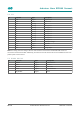
5.4 RP2040 SWD Pad
Pin Function Type Description
1 SWDIO Digital SWD Data Line
2 GND Digital Ground
3 SWCLK Digital SWD Clock
4 +3V3 Digital +3V3 Power Rail
5 TP_RESETN Digital Reset