
Reference Manual
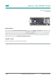


Arduino® Nano RP2040 Connect
10 / 19 Arduino® Nano RP2040 Connect Modified: 12/07/2022
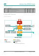
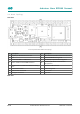
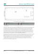
Back View of Arduino Nano RP2040 Connect Topology
Ref. Description Ref. Description
SJ4 3.3V jumper (connected) SJ1 VUSB jumper (disconnected)
3.3 Processor
The processor is based upon the new Raspberry Pi RP2040 silicon (U1). This microcontroller provides opportunities
for low-power Internet of Things (IoT) development and embedded machine learning. Two symmetric Arm®
Cortex®-M0+ clocked at 133MHz provide computation power for embedded machine learning and parallel
processing with low power consumption. Six independent banks of 264 KB SRAM and 2MB are provided. Direct
memory access provides fast interconnect between the processors and the memory that can be made inactive
along with the core to enter a sleep state. Serial wire debug (SWD) is available from boot via the pads under the
board. The RP2040 runs at 3.3V and has an internal voltage regulator providing 1.1V.
The RP2040 controls the peripherals and digital pins, as well as analog pins (A0-A3). The I2C connections on pins A4
(SDA) and A5 (SCL) are used for connecting to the onboard peripherals and are pulled up with a 4.7 kΩ resistor.
SWD Clock line (SWCLK) and reset are also pulled up with a 4.7 kΩ resistor. An external MEMS oscillator (U7)
running at 12MHz provides the clock pulse. Programmable IO helps to the implementation of arbitrary
communication protocol with minimal burden on the main processing cores. A USB 1.1 device interface is
implemented on the RP2040 for uploading code.