
Data Sheet
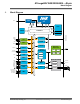
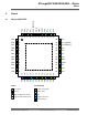

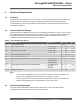
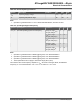
Table Of Contents
- Introduction
- Features
- Table of Contents
- 1. Block Diagram
- 2. Pinout
- 3. I/O Multiplexing and Considerations
- 4. Electrical Characteristics
- 4.1. Disclaimer
- 4.2. Absolute Maximum Ratings
- 4.3. General Operating Ratings
- 4.4. Power Considerations
- 4.5. Power Consumption
- 4.6. Peripherals Power Consumption
- 4.7. BOD and POR Characteristics
- 4.8. External Reset Characteristics
- 4.9. Oscillators and Clocks
- 4.10. I/O Pin Characteristics
- 4.11. USART
- 4.12. SPI
- 4.13. TWI
- 4.14. VREF
- 4.15. ADC
- 4.16. AC
- 4.17. UPDI Timing
- 4.18. Programming Time
- 5. Typical Characteristics
- 6. Ordering Information
- 7. Online Package Drawings
- 8. Package Drawings
- 9. Conventions
- 10. Data Sheet Revision History
- The Microchip Web Site
- Customer Change Notification Service
- Customer Support
- Product Identification System
- Microchip Devices Code Protection Feature
- Legal Notice
- Trademarks
- Quality Management System Certified by DNV
- Worldwide Sales and Service

– SleepWalking peripherals
• Power-Down with limited wake-up functionality
• Peripherals
– One 16-bit Timer/Counter type A (TCA) with a dedicated period register and three compare
channels
– Four 16-bit Timer/Counter type B with input capture (TCB)
– One 16-bit Real-Time Counter (RTC) running from an external crystal or an internal RC oscillator
– Four USART with fractional baud rate generator, auto-baud, and start-of-frame detection
– Master/slave Serial Peripheral Interface (SPI)
– Dual mode Master/Slave TWI with dual address match
• Standard mode (Sm, 100 kHz)
• Fast mode (Fm, 400 kHz)
• Fast mode plus (Fm+, 1 MHz)
– Event System for CPU independent and predictable inter-peripheral signaling
– Configurable Custom Logic (CCL) with up to four programmable Look-up Tables (LUT)
– One Analog Comparator (AC) with a scalable reference input
– One 10-bit 150 ksps Analog to Digital Converter (ADC)
– Five selectable internal voltage references: 0.55V, 1.1V, 1.5V, 2.5V, and 4.3V
– CRC code memory scan hardware
• Optional automatic scan before code execution is allowed
– Watchdog Timer (WDT) with Window mode, with separate on-chip oscillator
– External interrupt on all general purpose pins
• I/O and Packages:
– 41 programmable I/O lines
– 48-pin UQFN 6x6 and TQFP 7x7
• Temperature Range: -40°C to 125°C
• Speed Grades -40°C to 105°C:
– 0-5 MHz @ 1.8V – 5.5V
– 0-10 MHz @ 2.7V – 5.5V
– 0-20 MHz @ 4.5V – 5.5V
• Speed Grades -40°C to 125°C:
– 0-8 MHz @ 2.7V - 5.5V
– 0-16 MHz @ 4.5V - 5.5V
ATmega809/1609/3209/4809 – 48-pin
© 2019 Microchip Technology Inc.
Datasheet Preliminary
DS40002016B-page 2