
Data Sheet
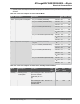
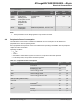
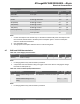
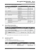

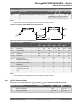
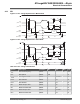
Table Of Contents
- Introduction
- Features
- Table of Contents
- 1. Block Diagram
- 2. Pinout
- 3. I/O Multiplexing and Considerations
- 4. Electrical Characteristics
- 4.1. Disclaimer
- 4.2. Absolute Maximum Ratings
- 4.3. General Operating Ratings
- 4.4. Power Considerations
- 4.5. Power Consumption
- 4.6. Peripherals Power Consumption
- 4.7. BOD and POR Characteristics
- 4.8. External Reset Characteristics
- 4.9. Oscillators and Clocks
- 4.10. I/O Pin Characteristics
- 4.11. USART
- 4.12. SPI
- 4.13. TWI
- 4.14. VREF
- 4.15. ADC
- 4.16. AC
- 4.17. UPDI Timing
- 4.18. Programming Time
- 5. Typical Characteristics
- 6. Ordering Information
- 7. Online Package Drawings
- 8. Package Drawings
- 9. Conventions
- 10. Data Sheet Revision History
- The Microchip Web Site
- Customer Change Notification Service
- Customer Support
- Product Identification System
- Microchip Devices Code Protection Feature
- Legal Notice
- Trademarks
- Quality Management System Certified by DNV
- Worldwide Sales and Service

...........continued
Peripheral Conditions Typ.
(1)
Unit
XOSC32K C
L
=7.5 pF 0.5 µA
OSCULP32K 0.4 µA
USART Enable @ 9600 Baud 13.0 µA
SPI (Master) Enable @ 100 kHz 2.1 µA
TWI (Master) Enable @ 100 kHz 24.0 µA
TWI (Slave) Enable @ 100 kHz 17.0 µA
Flash programming Erase Operation 1.5 mA
Write Operation 3.0
Note:
1. Current consumption of the module only. To calculate the total internal power consumption of the
microcontroller, add this value to the base power consumption given in “Power Consumption”
section in electrical characteristics.
2. CPU in Standby mode.
3. Average power consumption with ADC active in Free-Running mode.
4.7 BOD and POR Characteristics
Table 4-8. Power Supply Characteristics
Symbol Description Condition Min. Typ. Max. Unit
SRON
(1)
Power-on Slope - - 100
(2)
V/ms
Note:
1. For design guidance only and not tested in production.
2. A slope faster than the maximum rating can trigger a reset of the device if changing the voltage
level after an initial power-up.
Table 4-9. Power-on Reset (POR) Characteristics
Symbol Description Condition Min. Typ. Max. Unit
V
POR
POR threshold voltage on V
DD
falling
V
DD
falls/rises at 0.5V/ms or slower 0.8
(1)
- 1.6
(1)
V
POR threshold voltage on V
DD
rising
1.4
(1)
- 1.8
Note:
1. For design guidance only and not tested in production.
ATmega809/1609/3209/4809 – 48-pin
Electrical Characteristics
© 2019 Microchip Technology Inc.
Datasheet Preliminary
DS40002016B-page 14