
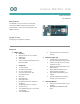
Product Data Sheet

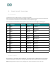
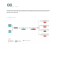

4. Connector Pinouts
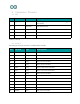
4.1 USB
Pin
Function
Type
Description
1
V
USB
Power
Power Supply Input. Output is board is powered via V
USB
from header
2
D-
Differential
USB differential data -
3
D+
Differential
USB differential data +
4
ID
Analog
Selects Host/Device functionality
5
GND
Power
Supply Ground
NOTE: This board can support USB host mode only if powered via the V
USB
pin and if the jumper close to the
VUSB pin is shorted.
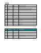
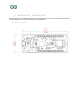
4.2 Headers
Board exposes two 28 pin connectors assembled with pin headers.
Pin
Function
Type
Description
1
AREF
Analog
Analog Reference.
2
A0/DAC0
Analog
ADC in/DAC out, Can be used as GPIO
3
A1
Analog
ADC in, Can be used as GPIO
4
A2
Analog
ADC in, Can be used as GPIO
5
A3
Analog
ADC in, Can be used as GPIO
6
A4/SDA
Analog
ADC in, I
2
C SDA, Can be used as GPIO
7
A5/SCL
Analog
ADC in, I
2
C SCL, Can be used as GPIO
8
A6
Analog
ADC in, Can be used as GPIO
9
D0
Digital
GPIO, can be used as PWM
10
D1
GPIO, can be used as PWM
11
D2/PWM
Digital
GPIO, can be used as PWM
12
D3/PWM
Digital
GPIO, can be used as PWM
13
D4/PWM
Digital
GPIO, can be used as PWM
14
D5/PWM
Digital
GPIO, can be used as PWM