
Datasheet


OSH: Schematics
The MKR GSM 1400 is open-source hardware! You can build your own board using the following files:
EAGLE FILES IN .ZIPSCHEMATICS IN .PDFFRITZING IN .FZPZ
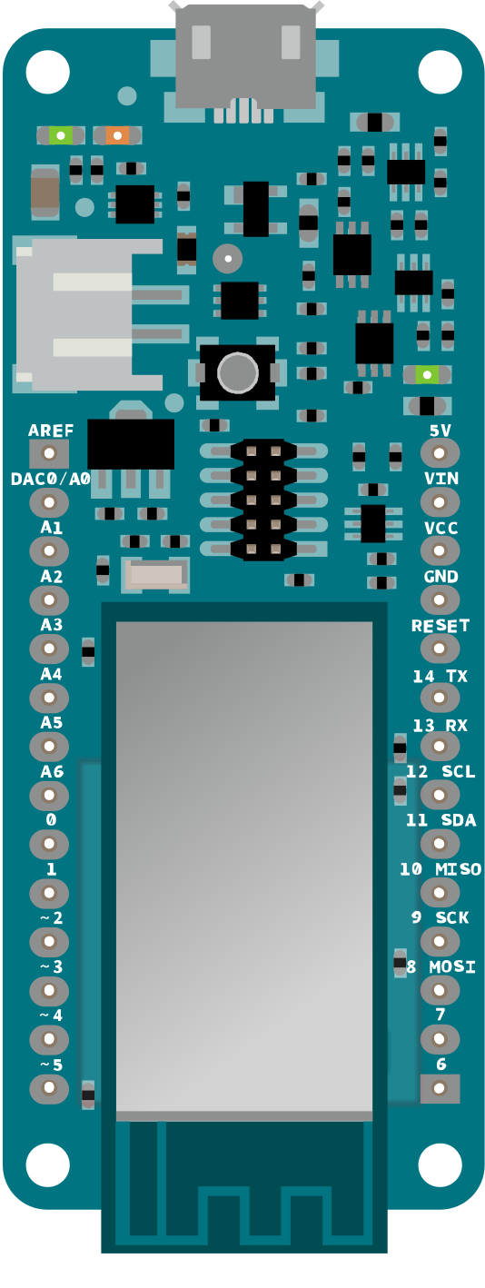
Pinout
Download the pinout in PNG format
Antenna
The MKR GSM 1400 has to be used with a GSM antenna that can be attached to the board with the micro
UFL connector.
Please check that it can accept frequencies in the GSM's range (880/915 MHz).
Please note: for best result, do not attach the antenna to a metallic surface like car chassis, etc.
Batteries, Pins and board LEDs
Battery capacity: The connected battery must be a 3.7V LiPo
Vin: This pin can be used to power the board with a regulated voltage source rated from 5V. If the power is
fed through this pin, the USB power source is disconnected. This is the only way you can supply 5v (range
is 5V to maximum 6V) to the board not using USB. This pin is an INPUT.
5V: This pin outputs 5V from the the board when powered from the USB connector or from the VIN pin of
the board. It is unregulated and the voltage is taken directly from the inputs.