
Datasheet


Table Of Contents
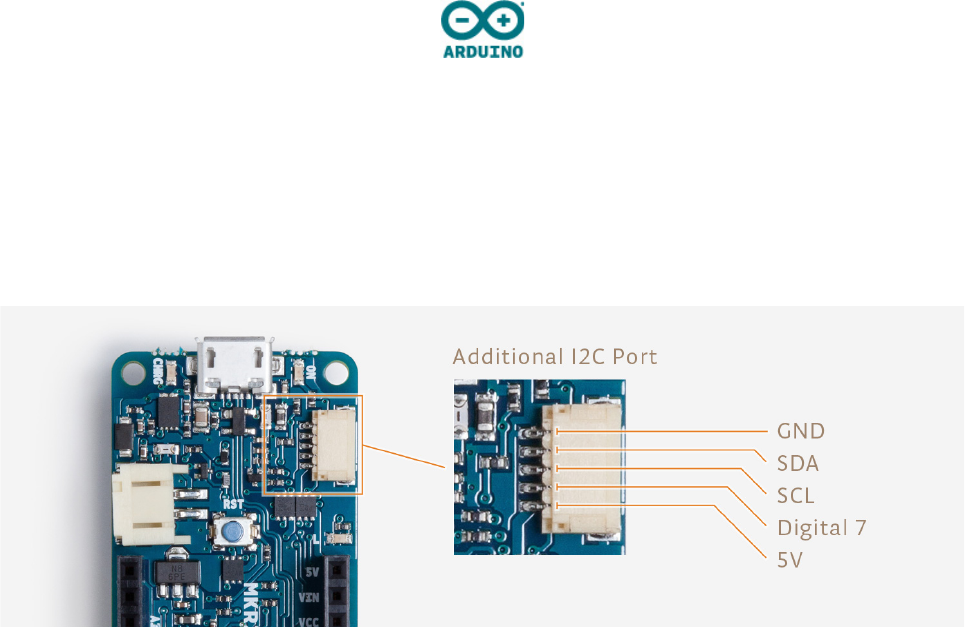
Additional I2C Port
The MKRZero has an additional connector meant as an extension of the I2C bus. It's a small form factor 5-
pin connector with 1.0mm pitch. The mechanical details of the connector can be found in the connector
datasheet. The I2C port in addition to the SDA and SCL signals includes the GND and +5V power rails
and a digital pin that might be useful when designing an expansion. The pinout is shown in the following
image:
Vin
This pin can be used to power the board with a regulated 5V source. If the power is fed through this pin,
the USB power source is disconnected. This is the only way you can supply 5v (range is 5V to maximum
6V) to the board not using USB. This pin is an INPUT.
5V
This pin outputs 5V from the the board when powered from the USB connector or from the VIN pin of the
board. It is unregulated and the voltage is taken directly from the inputs. As an OUTPUT, it should not be
used as an input pin to power the board.
VCC
This pin outputs 3.3V through the on-board voltage regulator. This voltage is the same regardless the
power source used (USB, Vin and Battery).
LED ON
This LED is connected to the 5V input from either USB or VIN. It is not connected to the battery power.
This means that it lits up when power is from USB or VIN, but stays off when the board is running on
battery power. This maximizes the usage of the energy stored in the battery. It is therefore normal to have
the board properly running on battery power without the LED ON being lit.
CHARGE LED
The CHARGE LED on the board is driven by the charger chip that monitors the current drawn by the Li-Po
battery while charging. Usually it will lit up when the board gets 5V from VIN or USB and the chip starts
charging the Li-Po battery connected to the JST connector. There are several occasions where this LED