
Data Sheet

Schematic: arduino-mega2560-schematic.pdf
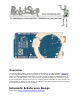
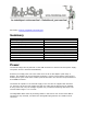
Summary
Microcontroller ATmega2560
Operating Voltage 5V
Input Voltage (recommended) 7-12V
Input Voltage (limits) 6-20V
Digital I/O Pins 54 (of which 14 provide PWM output)
Analog Input Pins 16
DC Current per I/O Pin 40 mA
DC Current for 3.3V Pin 50 mA
Flash Memory 256 KB of which 8 KB used by bootloader
SRAM 8 KB
EEPROM 4 KB
Clock Speed 16 MHz
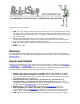
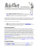
Power
The Arduino Mega can be powered via the USB connection or with an external power supply.
The power source is selected automatically.
External (non-USB) power can come either from an AC-to-DC adapter (wall-wart) or
battery. The adapter can be connected by plugging a 2.1mm center-positive plug into the
board's power jack. Leads from a battery can be inserted in the Gnd and Vin pin headers of
the POWER connector.
The board can operate on an external supply of 6 to 20 volts. If supplied with less than
7V, however, the 5V pin may supply less than five volts and the board may be unstable.
If using more than 12V, the voltage regulator may overheat and damage the board. The
recommended range is 7 to 12 volts.
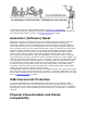
The Mega2560 differs from all preceding boards in that it does not use the FTDI USB-to-
serial driver chip. Instead, it features the Atmega8U2 programmed as a USB-to-serial
converter.