Arduino Mega 2560 Datasheet
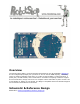
Overview The Arduino Mega 2560 is a microcontroller board based on the ATmega2560 (datasheet). It has 54 digital input/output pins (of which 14 can be used as PWM outputs), 16 analog inputs, 4 UARTs (hardware serial ports), a 16 MHz crystal oscillator, a USB connection, a power jack, an ICSP header, and a reset button. It contains everything needed to support the microcontroller; simply connect it to a computer with a USB cable or power it with a ACto-DC adapter or battery to get started.
Schematic: arduino-mega2560-schematic.pdf Summary Microcontroller Operating Voltage Input Voltage (recommended) Input Voltage (limits) Digital I/O Pins Analog Input Pins DC Current per I/O Pin DC Current for 3.3V Pin Flash Memory SRAM EEPROM Clock Speed ATmega2560 5V 7-12V 6-20V 54 (of which 14 provide PWM output) 16 40 mA 50 mA 256 KB of which 8 KB used by bootloader 8 KB 4 KB 16 MHz Power The Arduino Mega can be powered via the USB connection or with an external power supply.
The power pins are as follows: ● ● ● ● VIN. The input voltage to the Arduino board when it's using an external power source (as opposed to 5 volts from the USB connection or other regulated power source). You can supply voltage through this pin, or, if supplying voltage via the power jack, access it through this pin. 5V. The regulated power supply used to power the microcontroller and other components on the board.
● value, the LED is on, when the pin is LOW, it's off. I2C: 20 (SDA) and 21 (SCL). Support I2C (TWI) communication using the Wire library (documentation on the Wiring website). Note that these pins are not in the same location as the I2C pins on the Duemilanove or Diecimila. The Mega2560 has 16 analog inputs, each of which provide 10 bits of resolution (i.e. 1024 different values).
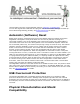
communicates using the original STK500 protocol (reference, C header files). You can also bypass the bootloader and program the microcontroller through the ICSP (InCircuit Serial Programming) header; see these instructions for details. Automatic (Software) Reset Rather then requiring a physical press of the reset button before an upload, the Arduino Mega2560 is designed in a way that allows it to be reset by software running on a connected computer.
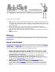
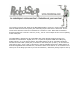
The maximum length and width of the Mega2560 PCB are 4 and 2.1 inches respectively, with the USB connector and power jack extending beyond the former dimension. Three screw holes allow the board to be attached to a surface or case. Note that the distance between digital pins 7 and 8 is 160 mil (0.16"), not an even multiple of the 100 mil spacing of the other pins. The Mega2560 is designed to be compatible with most shields designed for the Uno, Diecimila or Duemilanove.