ArduCAM Camera Shield Series SPI Camera Software Application Note Rev 3.
ArduCAM Camera Shield Software Application Note Table of Contents 1 Introduction ............................................................................................................................. 4 2 Software Library Structure .................................................................................................... 4 3 Quick Start Guide ................................................................................................................... 4 4 Example Sketches .............
ArduCAM Camera Shield Software Application Note 4.4.2 ArduCAM_ESP8266_Nano_Vx_Capture ................................................................... 10 4.4.3 ArduCAM_ESP8266_UNO_Vx _Capture2SD ........................................................... 10 4.4.4 ArduCAM_ESP8266_UNO_Vx_Video2SD ................................................................ 10 4.4.5 ArduCAM_ESP8266_Nano_Vx _Capture2SD ........................................................... 10 4.4.
ArduCAM Camera Shield Software Application Note 6.25 void OV5642_set_RAW_size (uint8_t size) ................................................................. 16 6.26 void set_format(byte fmt) ............................................................................................. 16 6.27 void OVxxxx_set_Light_Mode(uint8_t Light_Mode) ................................................ 16 6.28 void OVxxxx_set_Color_Saturation(uint8_t Color_Saturation) .............................. 16 6.
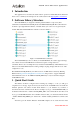
ArduCAM Camera Shield Software Application Note 1 Introduction This application note describes the detail software operation of ArduCAM camera shield. The latest source code library and examples can be downloaded from the https://github.com/arducam. 2 Software Library Structure The ArdCAM library is designed for Arduino platform,which is composed by three sub-libraries ArduCAM and ArduCAM_Touch and UTFT4ArduCAM_SPI.
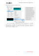
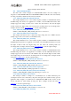
ArduCAM Camera Shield Software Application Note File->Examples->ArduCAM as the Figure 2 shown. Figure 2 Arduino IDE examples Open one of the examples, wiring SPI and I2C interface especially CS pins to ArduCAM shield according to the examples. More information about the wiring can be found from ArduCAM hardware application note. Selecting correct COM port and Arduino boards then upload the sketches as the Figure 3 shown. 5 www.ArduCAM.
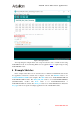
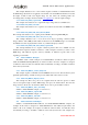
ArduCAM Camera Shield Software Application Note Figure 3 Example Sketch After uploading the example sketch, user can preview the live video on LCD screen if using ArduCAM-LF model. Or downloading Windows host application here to capture image if using ArduCAM Mini model. 4 Example Sketches In the example folder there are six sub directories for different ArduCAM models and the host application. Directories structure lists as Figure 4 shown. The ESP8266 folder is for ArduCAM-ESP8266-UNO board examples.
ArduCAM Camera Shield Software Application Note 7 www.ArduCAM.
ArduCAM Camera Shield Software Application Note Figure 4 Example Folder Structure 4.1 ArduCAM Mini Examples The mini folder contains examples for ArduCAM Mini shields. All of the examples are designed for ArduCAM-Mini-2MP and ArduCAM-Mini-5MP, and will take effect automatically according to the Macro definition in the memorysaver.h file. 4.1.
ArduCAM Camera Shield Software Application Note This example illustrates how to send continues capture commands to ArduCAM and transfer the JPEG image data back to host application via Arduino onboard USB-Serial interface. Note that the higher resolution wills cause higher image size and reduce the streaming frame rate accordingly. These examples should work with host application to view the captured images. 4.1.
ArduCAM Camera Shield Software Application Note work with ArduCAM-Nano-ESP8266 module. 4.3.1 ArduCAM_Shield_V2_Camera_Playback Similar to ArduCAM-REVC example, see section 4.2.1. 4.3.2 ArduCAM_ Shield_V2_Digital_Camera Similar to ArduCAM-REVC example, see section 4.2.2. 4.3.3 ArduCAM_ Shield_V2_Video_Streaming Similar to ArduCAM-Mini example, see section 4.1.4. 4.3.4 ArduCAM_ Shield_V2_Multi_Capture2SD Similar to ArduCAM-Mini example, see section 4.1.17. 4.3.
ArduCAM Camera Shield Software Application Note Similar to ArduCAM ESP8266 UNO Video2SD , see section 4.4.4. 4.4.7 ArduCAM_ESP8266_Nano_V2_DeepSleep This example illustrates how to disable unwanted power consumption from the sensor and memory chip after each capture. It is useful for battery powered application. 4.5 RasberryPi Examples 4.5.1 arducam_ovxx_capture This example illustrates how to capture picture on raspberry pi using arducam 2MP/5MP camera 4.5.
ArduCAM Camera Shield Software Application Note make the frame buffer overflow. 5.3 Short Video Capture Mode Use the same command as the Multiple Capture Mode. When the value bit[2:0] equals to 7, the ArduCAM will continuously capture the images until the entire frame buffer is full. User can save the captured MJPEG to AVI files to create short movie clips. 5.4 Single Read Operation It is basic memory read function which start a single read operation and read a single byte each time.
ArduCAM Camera Shield Software Application Note It is achieved by controlling the power enable pin of the onboard LDOs. The power enable pin is controlled by the GPIO[2] of ArduChip. By sending the command code 0x86 and write ‘1’ to bit[2] to enable the LDOs, or write ‘0’ to bit[2] to disable the LDOs to save power. Note that power down the sensor circuit, the camera settings are lost. User should reinitialize the sensor when power up the sensor circuit again. 5.7.
ArduCAM Camera Shield Software Application Note Return value: error status wrSensorRegs8_8 function is used to write array of settings into sensor’s internal register over I2C interface and sensor’s register is accessed with 8bit address and 8bit data. 6.
ArduCAM Camera Shield Software Application Note Param2: value read from the register Return value: error status rdSensorReg8_8 function is used to read a single sensor’s internal register value over I2C interface and sensor’s register is accessed with 8bit address and 8bit data. 6.
ArduCAM Camera Shield Software Application Note #define OV3640_1280x960 #define OV3640_1600x1200 #define OV3640_2048x1536 6 7 8 //1280x960 //1600x1200 //2048x1536 6.23 void OV5642_set_JPEG_size(uint8_t size) Param1: resolution code OV5642_set_JPEG_size function is used to set the desired resolution with JPEG format for OV5642.
ArduCAM Camera Shield Software Application Note For different sensors, the parameters may be different (Specific reference SDK source code). 6.29 void OVxxxx_set_Brightness(uint8_t Brightness) OVxxxx_set_Brightness function is used to set the brightness for arducam. For different sensors, the parameters may be different (Specific reference SDK source code). 6.30 void OVxxxx_set_Contrast(uint8_t Contrast) OVxxxx_set_Contrast function is used to set the contrast for arducam.
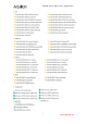
ArduCAM Camera Shield Software Application Note 7 Registers Table Sensor and FIFO timing is controlled with a set of registers which is implemented in the ArduChip. User can send capture commands and read image data with a simple SPI slave interface. The detail description of registers’ bits can be found in the software section in this document.
ArduCAM Camera Shield Software Application Note Bit[2]: Sensor power enable IO direction 0 = input, 1 = output 0x06 RW GPIO Write Register Bit[0]: Sensor reset IO value Bit[1]: Sensor power down IO value Bit[2]: Sensor power enable IO value 0x3B RO Reserved 0x3C RO Burst FIFO read operation 0x3D RO Single FIFO read operation 0x3E WO LCD control register with RS=0 0x3F WO LCD control register with RS=1 0x40 RO ArduChip version Bit[7:4]: integer part of the revision number Bit[3:0]: decim