
User Guide
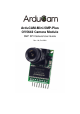


ArduCAM-Mini-5MP-Plus Camera User Guide
www.ArduCAM.com
5
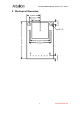
7.4 Eternal Hardware Trigger
External hardware trigger input (Active High) can be used to start a capture manually,
software part only needs to polling the "capture done" status bit before reading the image data.
Figure 3 shows the hardware pins for trigger.
Figure 2 Hardware Trigger Pins
7.5 JPEG Compression
The JPEG compression function is implemented in the image sensor. With proper register
settings to the sensor, user can get different resolution with JPEG image stream output. It is
recommended to use JPEG output to get higher resolution than RGB mode, due to the limitation
of frame buffer.
7.6 Normal Read and Burst Read Operation
Normal read operation reads each image data by sending a read command in one SPI read
operation cycle. While burst read operation only need to send a read command then read multiple
image data in one SPI read operation cycle. It is recommended to use burst read operation to get
better throughput performance.
7.7 Rewind Read Operation
Sometimes user wants to read the same frame of image data multiple times for processing,
the rewind read operation is designed for this purpose. By resetting the read pointer to the
beginning of the image data, user can read the same image data from the start point again.
7.8 Low Power Mode
Some battery power device need save power when in the idle status, the ArduCAM offers the
low power mode to reduce power consumption, by shutdown the sensor circuits.
7.9 Image Sensor Control
Image sensor control function is implemented in the image sensor. By setting proper set of
register settings, user can control the exposure, white balance, brightness, contrast, color
saturation and etc.
More technical information about ArduCAM mini shield, please read
ArduCAM-Mini-5MP-Plus Hardware Application Note.pdf and ArduCAM Software Application
Note.pdf for detail.