
User Guide


ArduCAM-Mini-5MP-Plus Camera User Guide
www.ArduCAM.com
4
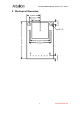
6 Block Diagram
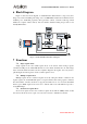
Figure 2 shows the block diagram of ArduCAM mini shield which is composed by lens,
image sensor and an ArduChip. The image sensor is 5MP CMOS OV5642 from Omnivision. The
ArduChip uses ArduCAM proprietary third generation camera controller technology which
handles the complex camera, memory and user interface hardware timing and provides a user
friendly SPI interface.
Off Chip
Memory
REG
Module
SPI Slave
Memory
Timing
Frame
Buffer FSM
ArduChip
Block Diagram
Camera Interface
Image
Sensor
Lens
CS
MISO
MOSI
SCLK
SCL
SDA
Trigger
Figure 2 ArduCAM Mini Shield Block Diagram
7 Functions
7.1 Single Capture Mode
Single capture mode is the default capture mode of the camera. After issuing a capture
command via SPI port, the ArduCAM will wait for a new frame and buffer the one entire image
data to the frame buffer, and then assert the completion flag bit in the register. User only needs to
poll the flag bit from the register to check out if the capture is done.
7.2 Multiple Capture Mode
Multiple capture mode is advanced capture mode. By setting the number of frames in the
capture register, the ArduCAM will capture consequent frames after issuing capture command.
Note that number of frames should be set properly and make sure do not exceed the maximum
memory space. Multi capture mode can be use to take the same scene with different exposure to
create HDR images.
7.3 Short Movie Capture Mode
Short movie capture mode is the continuous capture mode until the 8MByte frame is full.
User can use this mode record couple of seconds video and save to AVI file into SD card.