
Application Notes

ArduCAM-Mini-5MP-Plus Hardware Application Note
www.ArduCAM.com
3
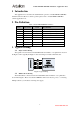
Arduino
Maple
Chipkit
Raspberry Pi
BeagleBone Black
CS0n
MISO
MOSI
SCLK
SCL
SDA
+5V
GND
CS1n
CS2n
CS3n
ArduCAM
Mini
5MP-Plus
CSn
MISO
MOSI
SCLK
SCL
SDA
VCC
GND
ArduCAM
Mini
5MP-Plus
CSn
MISO
MOSI
SCLK
SCL
SDA
VCC
GND
ArduCAM
Mini
5MP-Plus
CSn
MISO
MOSI
SCLK
SCL
SDA
VCC
GND
ArduCAM
Mini
5MP-Plus
CSn
MISO
MOSI
SCLK
SCL
SDA
VCC
GND
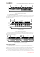
Figure 3 Multi-Cameras Wiring
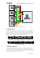
4 I2C Interface
The I2C interface is directly connected to the image sensor OV5642. The OV5642 I2C slave
address is 0x78 for write and 0x79 for read. User can use I2C master to read and write all the
registers in the OV5642 sensor. For more information about the OV5642 register, please refer the
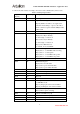
OV5642 datasheet. The Figure 4 shows writing value 0x80 to the OV5642 register 0x3008. The
Figure 5 shows reading value 0x56 from the OV5642 register 0x300A.
SCL
SDA
START
0x78 ADDR
ACK ACK
RegH 0x30 1000 0000
ACK STOPACK
RegL 0x08
Figure 4 I2C Write Bus Timing
SCL
SDA
START
0x78 ADDR
ACK ACK
RegH 0x30 0101 0110
NACK
0x79 ADDR
ACKSTARTACK
RegL 0x0A
Figure 5 I2C Read Bus Timing
5 SPI Slave Interface
The ArduCAM SPI slave interface is fixed SPI mode 0 with POL = 0 and PHA = 0. The
stable SCLK speed is 8MHz, care should be taken when over clock the SPI bus speed. The SPI
protocol is designed with a command phase with variable data phase. The chip select signal should
always keep asserted during the SPI read or write bus cycle.