
Application Notes

ArduCAM-Mini-5MP-Plus Hardware Application Note
www.ArduCAM.com
2
1 Introduction
This application note describes the detail hardware operation of ArduCAM-Mini-5MP-Plus
OV5642 camera module. For software operation please refer to ArduCAM-Mini-5MP-Plus
software application note.
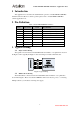
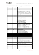
2 Pin Definition
Table 1 ArduCAM-M-5MP Pin Definition
Pin No.
PIN NAME
TYPE
DESCRIPTION
1
CS
Input
SPI slave chip select input
2
MOSI
Input
SPI master output slave input
3
MISO
Output
SPI master input slave output
4
SCLK
Input
SPI serial clock
5
GND
Ground
Power ground
6
VCC
POWER
3.3V~5V Power supply
7
SDA
Bi-directional
Two-Wire Serial Interface Data I/O
8
SCL
Input
Two-Wire Serial Interface Clock
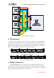
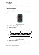
3 Typical Wiring
3.1 Single Camera Wiring
The typical connection between ArduCAM module and Arduino or etc platform is shown in
the Figure 1. More typically the Figure 2 shows the wiring for Arduino UNO R3 board.
ArduCAM Module
CSn
MISO
MOSI
SCLK
Arduino
Maple
Chipkit
Raspberry Pi
BeagleBone Black
SCL
SDA
+5V
GND
Trigger
Figure 1 Typical Wiring
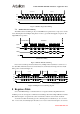
3.2 Multi Cameras Wiring
The multi-cameras connection between ArduCAM module and Arduino or etc platform is
shown in the Figure 3. Please note that the 5MP-Plus camera uses massive power, so connecting
multiple cameras you should use external power supply.