
Low Distortion IMX219 M12 Mount Camera Module for Raspberry Pi - Datasheet
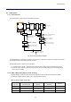
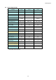
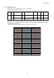
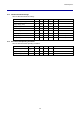
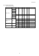
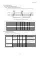
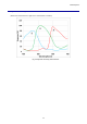
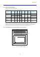
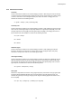
Table Of Contents
- Description
- Features
- Device Structure
- USE RESTRICTION NOTICE
- 1. Block Diagram and Pin Configuration
- 2. Pixel Signal Output Specifications
- 3. Control Registers
- 3-1 2-wire Serial Communication Operation Specifications
- 3-2 2-wire Serial Communication Register Map (Configuration register, Parameter limit register)
- 3-3 Parameter Limit Registers – [0x1000-0x1FFF] (Read Only and Static)
- 3-4 Manufacturer Specific Registers – [0x3000-0x5FFF ]
- 3-5 Frame Bank A and Bank B specific output samples
- 4. Output Data Format
- 6. On Chip Image Processing
- 7. NVM Memory Map
- 8. How to operate IMX219PQH5-C
- 9. Other Functions
- 10. Electrical Characteristics
- 11. Spectral Sensitivity Characteristic
- 12. Image Sensor Characteristics
- 13. Measurement Method for Image Sensor Characteristics
- 14. Spot Pixel Specification
- 15. Notice on White Pixels Specifications
- 16. Chief Ray Angle Characteristics
- 17. Connection Example
- 18. Notes On Handling

IMX219PQH5-C
89
13. Measurement Method for Image Sensor Characteristics
13-1 Measurement conditions
The device operation conditions are at the typical values of the bias and clock voltage.
Table 47 Measurement Conditions
Supply voltage
Analog 2.8 V, digital 1.2 V, IF 1.8 V
Clock
INCK (EXTCLK) 18 MHz
In the following measurements, spot pixels are excluded and, unless otherwise specified, the optical black
(OB) level is used as the reference for the signal output, which is taken as the value of the Gr, Gb, R and B
digital signal outputs of the measurement system.
0.357 mV in all-pixel output 10-bit operation mode.
13-2 Color Coding of This Image Sensor and Readout
The primary color filters of this image sensor are arranged in the layout shown in the figure below. Gr and Gb
denote the G signals on the same line as the R signal and the B signal, respectively. The R signal and Gr signal
lines and the Gb signal and B signal lines are output successively.
All pixel signals are output successively in a 1/15 s period.
Fig. 47 Color coding alignment
13-3 Definition of Standard Imaging Conditions
Standard imaging condition I
Use a pattern box (luminance: 706 cd/m2, color temperature of 3200 K halogen source) as a subject.
(Pattern for evaluation is not applicable.) Use a testing standard lens with CM500S (t = 1.0 mm) as an IR cut
filter and image at F2.8. The luminous intensity to the sensor receiving surface at this point is defined as the
standard sensitivity testing luminous intensity.
Standard imaging condition II
A testing lens with CM500S (t = 1.0 mm) is used as an IR cut filter for light source with 3200 K color
temperature. The luminous intensity to the sensor receiving surface is adjusted to the luminous intensity
level shown in each measurement item by the light source output, lens aperture or storage time control by
the electronic shutter.
Standard imaging condition III
A recommended testing lens with CM500S (t = 1.0 mm) is used as an IR cut filter for light source with 3200 K
color temperature. The luminous intensity to the sensor receiving surface is adjusted to the luminous intensity
level shown in each measurement item by the light source output or storage time control by the electronic
shutter.
Gb B
R Gr
Gb B
R Gr
Gb B
R Gr
Gb B
R Gr
Gb B
R Gr
Gb B
R Gr
Gb B
R Gr
Gb B
R Gr
Gb B
R Gr