
Low Distortion IMX219 M12 Mount Camera Module for Raspberry Pi - Datasheet
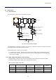
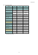
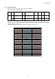
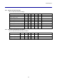
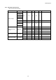
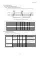
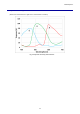
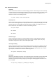
Table Of Contents
- Description
- Features
- Device Structure
- USE RESTRICTION NOTICE
- 1. Block Diagram and Pin Configuration
- 2. Pixel Signal Output Specifications
- 3. Control Registers
- 3-1 2-wire Serial Communication Operation Specifications
- 3-2 2-wire Serial Communication Register Map (Configuration register, Parameter limit register)
- 3-3 Parameter Limit Registers – [0x1000-0x1FFF] (Read Only and Static)
- 3-4 Manufacturer Specific Registers – [0x3000-0x5FFF ]
- 3-5 Frame Bank A and Bank B specific output samples
- 4. Output Data Format
- 6. On Chip Image Processing
- 7. NVM Memory Map
- 8. How to operate IMX219PQH5-C
- 9. Other Functions
- 10. Electrical Characteristics
- 11. Spectral Sensitivity Characteristic
- 12. Image Sensor Characteristics
- 13. Measurement Method for Image Sensor Characteristics
- 14. Spot Pixel Specification
- 15. Notice on White Pixels Specifications
- 16. Chief Ray Angle Characteristics
- 17. Connection Example
- 18. Notes On Handling

IMX219PQH5-C
88
12. Image Sensor Characteristics
12-1 Image Sensor Characteristics
Table 46 Image Sensor Characteristics
(30 frame/s, V
ANA
= 2.8 V, V
DIG
= 1.2 V, V
IF
= 1.8 V, Tj = 60 )
Item
Symbol
Min.
Typ.
Max.
Unit
Range
Measur
ement
method
Remarks
Sensitivity
S
205
LSB
Center
1
1/120 s storage
Sensitivity ratio
RG
0.45
0.51
0.57
Center
2
BG
0.40
0.46
0.52
Saturation signal
Vsat
1023
LSB
Zone1
3
Video signal
shading
SH
70
%
Zone2D
4
Design assurance
Dark signal
Vdt
0.5
LSB
Zone2D
5
When operation at
15 frame/s
LSB is the abbreviation of Least Significant Bit. 10 bits = 1023 digital is the maximum output code for the output unit.
The base gain in which the saturation signal output matches with 1023 LSB is 0[dB] when the OB level is 64 LSB
(standard recommended value). The data described at this image sensor characteristics are the measurement
standard without base gain setting, and indicates the results evaluated with OB as a reference.
12-2 Zone Definition used for specifying image sensor characteristics
Fig. 46 Zone Definition Diagram
Zone1
Zone2D
Zone3
16
16
OB side ignored area
Effective OB
2
8
OB side ignored area
Dummy
(1, 43)
(9, 51)
(413, 291)
(3296, 2522)
(2884, 2274)
(3288, 2514)
(9, 11)
(3288, 26)