
Low Distortion IMX219 M12 Mount Camera Module for Raspberry Pi - Datasheet
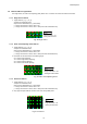
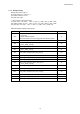
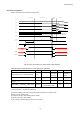
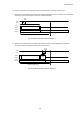
Table Of Contents
- Description
- Features
- Device Structure
- USE RESTRICTION NOTICE
- 1. Block Diagram and Pin Configuration
- 2. Pixel Signal Output Specifications
- 3. Control Registers
- 3-1 2-wire Serial Communication Operation Specifications
- 3-2 2-wire Serial Communication Register Map (Configuration register, Parameter limit register)
- 3-3 Parameter Limit Registers – [0x1000-0x1FFF] (Read Only and Static)
- 3-4 Manufacturer Specific Registers – [0x3000-0x5FFF ]
- 3-5 Frame Bank A and Bank B specific output samples
- 4. Output Data Format
- 6. On Chip Image Processing
- 7. NVM Memory Map
- 8. How to operate IMX219PQH5-C
- 9. Other Functions
- 10. Electrical Characteristics
- 11. Spectral Sensitivity Characteristic
- 12. Image Sensor Characteristics
- 13. Measurement Method for Image Sensor Characteristics
- 14. Spot Pixel Specification
- 15. Notice on White Pixels Specifications
- 16. Chief Ray Angle Characteristics
- 17. Connection Example
- 18. Notes On Handling

IMX219PQH5-C
80
To in power-off sequence varies depending on the CCI communication end timing as shown below.
1. When the CCI communication is performed with Software Standby between SOF and EOF, all communicated
frame data is output and the status is converted to Software Standby.
Fig. 41 Software Standby Operation Pattern 1
2. When the CCI communication is performed with Software Standby during FrameBlanking, the status is
converted to Software Standby immediately after communication.
Fig. 42 Software Standby Operation Pattern 2
S
O
F
E
O
F
N 0xFF
SDA
SCL
CSI2
DATA
Frame
Counter
Enter
Stop
Frame_length_lines
Frame
Blanking
S
O
F
E
O
F
N 0xFF
SDA
SCL
CSI2
DATA
Frame
Counter
Enter
Stop
Frame_length_lines