
Low Distortion IMX219 M12 Mount Camera Module for Raspberry Pi - Datasheet
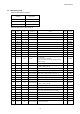

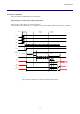
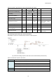
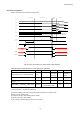
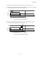
Table Of Contents
- Description
- Features
- Device Structure
- USE RESTRICTION NOTICE
- 1. Block Diagram and Pin Configuration
- 2. Pixel Signal Output Specifications
- 3. Control Registers
- 3-1 2-wire Serial Communication Operation Specifications
- 3-2 2-wire Serial Communication Register Map (Configuration register, Parameter limit register)
- 3-3 Parameter Limit Registers – [0x1000-0x1FFF] (Read Only and Static)
- 3-4 Manufacturer Specific Registers – [0x3000-0x5FFF ]
- 3-5 Frame Bank A and Bank B specific output samples
- 4. Output Data Format
- 6. On Chip Image Processing
- 7. NVM Memory Map
- 8. How to operate IMX219PQH5-C
- 9. Other Functions
- 10. Electrical Characteristics
- 11. Spectral Sensitivity Characteristic
- 12. Image Sensor Characteristics
- 13. Measurement Method for Image Sensor Characteristics
- 14. Spot Pixel Specification
- 15. Notice on White Pixels Specifications
- 16. Chief Ray Angle Characteristics
- 17. Connection Example
- 18. Notes On Handling

IMX219PQH5-C
79
8-2 Power off sequence
Perform the power-off in the sequence shown below.
XCLR
CCI
INCK
CLK
+/-
Streaming (Active) Software Standby
Power Off
Hardware
Standby
t3
LP11
LP11
LP11
LP00
LP00
LP00
Data
1 &2 +/-
Data
3 & 4 +/-
t2
XCLR
(internal)
t1
t4
t5
VANA
VDIG
VDDL
VBAT
t0
Fig. 40 Power-off Sequence in 2-wire Serial Communication
Table 38 Operation Specifications in 2-wire Serial Communication
Constraint
Label
Min.
Max.
Units
Comment
Communication end Software standby
t0
One frame
time (*1)
s
Until frame
output
Software standby - XCLR H
t1
0
ns
Falling time of internal XCLR after
XCLR H
t2
10
µs
VANA falling - VDIG falling - VDDL falling
t3,t4,t5
VANA, VDIG and VDDL
may fall in any order.
ns
(*1) One frame time = 1/(Frame_Rate[frame/s])
Can set fast standby mode when fast standby register (0x0106)] set to enable (0x01).
Sequence for fast standby mode;
(1) 0x0106 set to 0x01 ( fast standby mode is enable)
(2) 0x0100 set to 0x00 ( SW standby )
(3) Can change to SW standby after read out of current line.