
Low Distortion IMX219 M12 Mount Camera Module for Raspberry Pi - Datasheet
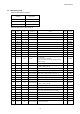
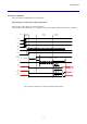
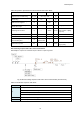
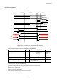
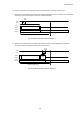
Table Of Contents
- Description
- Features
- Device Structure
- USE RESTRICTION NOTICE
- 1. Block Diagram and Pin Configuration
- 2. Pixel Signal Output Specifications
- 3. Control Registers
- 3-1 2-wire Serial Communication Operation Specifications
- 3-2 2-wire Serial Communication Register Map (Configuration register, Parameter limit register)
- 3-3 Parameter Limit Registers – [0x1000-0x1FFF] (Read Only and Static)
- 3-4 Manufacturer Specific Registers – [0x3000-0x5FFF ]
- 3-5 Frame Bank A and Bank B specific output samples
- 4. Output Data Format
- 6. On Chip Image Processing
- 7. NVM Memory Map
- 8. How to operate IMX219PQH5-C
- 9. Other Functions
- 10. Electrical Characteristics
- 11. Spectral Sensitivity Characteristic
- 12. Image Sensor Characteristics
- 13. Measurement Method for Image Sensor Characteristics
- 14. Spot Pixel Specification
- 15. Notice on White Pixels Specifications
- 16. Chief Ray Angle Characteristics
- 17. Connection Example
- 18. Notes On Handling

IMX219PQH5-C
78
Table 36 Operation Specifications 2-wire Serial Communication Mode
Constraint
Label
Min.
Max.
Units
Comment
Sequence free of VDDs rising
t0, t1, t2
VANA, VDIG, VDDL may
rise in any order.
ns
XCLR rising
t3
0.5
µs
Internal XCLR is Low to High after
VDDs & XCLR supplied
t4
200
µs
releasing software standby after
XCLR Low to High
t5
6
ms
charge up VRL
Initializing time of silicon
t6
32000
clocks
clock is INCK
Case of INCK = 6[MHz],
5.3[msec]
D-PHY power-up
t7
1
1.1
ms
D-PHY init
t8
100
110
µs
After releasing software standby to
data streaming time
t9
1.2 ms +
exposure time
Quick launch up time
t10
1
frame
stable time until optimal
image quality
Start streaming sequence with 2-wire serial communication
IMX219PQH5-C requires the command sequence below to output image data.
Fig. 39 Start streaming sequence with 2-wire serial communication (external reset)
Table 37 Initialization sequence with XCLR
(1) to (3)
Refer power up sequence timing diagram
(4)
Set PLL parameters
Basic setting (operation-critical setting)
Set Readout mode (start/end position, size, mode, integration time, and gain)
Set MIPI interface parameters
(5)
Start streaming with 0x0100 (mode_select = 1)
st
frame starts and images come out